ZHCSD68H July   2014  – April 2021 LSF0204 , LSF0204D

PRODUCTION DATA  

  1. 特性
  2. 应用
  3. 说明
  4. Revision History
  5. 说明(续)
  6. Pin Configuration and Functions
  7. Specifications
    1. 7.1  Absolute Maximum Ratings
    2. 7.2  ESD Ratings
    3. 7.3  Recommended Operating Conditions
    4. 7.4  Thermal Information
    5. 7.5  Electrical Characteristics
    6. 7.6  Switching Characteristics: AC Performance (Translating Down, 3.3 V to 1.8 V)
    7. 7.7  Switching Characteristics: AC Performance (Translating Down, 3.3 V to 1.2 V)
    8. 7.8  Switching Characteristics: AC Performance (Translating Up, 1.8 V to 3.3 V)
    9. 7.9  Switching Characteristics: AC Performance (Translating Up, 1.2 V to 1.8 V)
    10. 7.10 Typical Characteristics
  8. Parameter Measurement Information
    1. 8.1 Load Circuit AC Waveform for Outputs
  9. Detailed Description
    1. 9.1 Overview
    2. 9.2 Functional Block Diagram
    3. 9.3 Feature Description
      1. 9.3.1 Support High Speed Translation, Greater than 100 MHz
      2. 9.3.2 Bidirectional Voltage Translation Without DIR Terminal
      3. 9.3.3 5-V Tolerance on IO Port and 125°C Support
      4. 9.3.4 Channel Specific Translation
      5. 9.3.5 Ioff, Partial Power Down Mode
    4. 9.4 Device Functional Modes
  10. 10Application and Implementation
    1. 10.1 Application Information
    2. 10.2 Typical Applications
      1. 10.2.1 I2C PMBus, SMBus, GPIO, Application
        1. 10.2.1.1 Design Requirements
          1. 10.2.1.1.1 Enable, Disable, and Reference Voltage Guidelines
        2. 10.2.1.2 Detailed Design Procedure
          1. 10.2.1.2.1 Bidirectional Translation
            1. 10.2.1.2.1.1 Pull-Up Resistor Sizing
          2. 10.2.1.2.2 LS Family Bandwidth
        3. 10.2.1.3 Application Curve
      2. 10.2.2 MDIO Application
        1. 10.2.2.1 Design Requirements
        2. 10.2.2.2 Detailed Design Procedure
        3. 10.2.2.3 Application Curve
      3. 10.2.3 Multiple Voltage Translation in Single Device, Application
        1. 10.2.3.1 Design Requirements
        2. 10.2.3.2 Detailed Design Procedure
        3. 10.2.3.3 Application Curve
  11. 11Power Supply Recommendations
  12. 12Layout
    1. 12.1 Layout Guidelines
    2. 12.2 Layout Example
  13. 13Device and Documentation Support
    1. 13.1 接收文档更新通知
    2. 13.2 支持资源
    3. 13.3 Trademarks
    4. 13.4 Electrostatic Discharge Caution
    5. 13.5 术语表
  14. 14Mechanical, Packaging, and Orderable Information

封装选项

请参考 PDF 数据表获取器件具体的封装图。

机械数据 (封装 | 引脚)
  • RGY|14
  • YZP|12
  • RUT|12
  • PW|14
散热焊盘机械数据 (封装 | 引脚)
订购信息

说明

LSF 系列包含双向电压电平转换器,该转换器可在 0.8V 至 4.5V (Vref_A) 和 1.8V 至 5.5V (Vref_B) 电压范围内运行。该范围支持在 0.8V 和 5.0V 之间进行双向电压转换,无需在漏极开路或推挽应用中使用方向端子。对于采用 15pF 电容器和 165Ω 上拉电阻器的漏极开路系统,LSF 系列支持传输速度大于 100MHz 的电平转换应用。

当 An 或 Bn 端口为低电平时,此开关处于接通状态,而且 An 和 Bn 端口之间存在低电阻连接。开关的低 Ron 可实现具有超小传播延迟和信号失真的连接。A 端或 B 端的电压将限制为 Vref_A,且可上拉至 Vref_A 到 5V 之间的任何电压水平。利用此功能,可在无需方向控制的情况下,在用户选择的较高和较低电压之间实现无缝转换。

器件信息(1)
器件型号 封装 封装尺寸(标称值)
LSF0204x TSSOP (14) 5.00mm × 4.40mm
UQFN (12) 2.00mm × 1.70mm
VQFN (14) 3.50mm × 3.50mm
DSBGA (12) 1.90mm × 1.40mm
如需了解所有可用封装,请参阅数据表末尾的可订购产品附录。
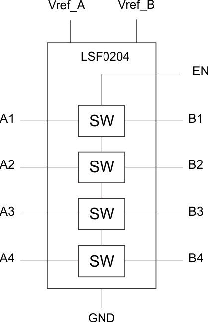
GUID-6B373509-C84A-4204-9029-4B5522FE270F-low.gif简化原理图