ZHCSIC9D April   2016  – June 2018 LMH1219

PRODUCTION DATA.  

  1. 特性
  2. 应用
  3. 说明
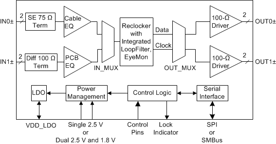
    1.     简化框图
  4. 修订历史记录
  5. Pin Configuration and Functions
    1.     Pin Functions
  6. Specifications
    1. 6.1 Absolute Maximum Ratings
    2. 6.2 ESD Ratings
    3. 6.3 Recommended Operating Conditions
    4. 6.4 Thermal Information
    5. 6.5 Electrical Characteristics
    6. 6.6 Recommended SMBus Interface AC Timing Specifications
    7. 6.7 Serial Parallel Interface (SPI) AC Timing Specifications
    8. 6.8 Typical Characteristics
  7. Detailed Description
    1. 7.1 Overview
    2. 7.2 Functional Block Diagram
    3. 7.3 Feature Description
      1. 7.3.1  4-Level Input Configuration Pins
      2. 7.3.2  Input Carrier Detect
      3. 7.3.3  -6 dB Splitter Mode Launch Amplitude for IN0
      4. 7.3.4  Continuous Time Linear Equalizer (CTLE)
        1. 7.3.4.1 Adaptive Cable Equalizer (IN0+)
        2. 7.3.4.2 Adaptive PCB Trace Equalizer (IN1±)
      5. 7.3.5  Input-Output Mux Selection
      6. 7.3.6  Clock and Data Recovery (CDR) Reclocker
      7. 7.3.7  Internal Eye Opening Monitor (EOM)
      8. 7.3.8  Output Function Control
      9. 7.3.9  Output Driver Amplitude and De-Emphasis Control
      10. 7.3.10 Status Indicators and Interrupts
        1. 7.3.10.1 LOCK_N (Lock Indicator)
        2. 7.3.10.2 CD_N (Carrier Detect)
        3. 7.3.10.3 INT_N (Interrupt)
      11. 7.3.11 Additional Programmability
        1. 7.3.11.1 Cable Length Indicator (CLI)
        2. 7.3.11.2 Digital MUTEREF
    4. 7.4 Device Functional Modes
      1. 7.4.1 System Management Bus (SMBus) Mode
        1. 7.4.1.1 SMBus Read and Write Transactions
          1. 7.4.1.1.1 SMBus Write Operation Format
          2. 7.4.1.1.2 SMBus Read Operation Format
      2. 7.4.2 Serial Peripheral Interface (SPI) Mode
        1. 7.4.2.1 SPI Read and Write Transactions
          1. 7.4.2.1.1 SPI Write Transaction Format
          2. 7.4.2.1.2 SPI Read Transaction Format
        2. 7.4.2.2 SPI Daisy Chain
    5. 7.5 LMH1219 Register Map
      1. 7.5.1 Share Register Page
      2. 7.5.2 CTLE/CDR Register Page
      3. 7.5.3 CableEQ/Drivers Register Page
  8. Application and Implementation
    1. 8.1 Application Information
      1. 8.1.1 General Guidance for SMPTE and 10 GbE Applications
      2. 8.1.2 Optimizing Time to Adapt and Lock
      3. 8.1.3 LMH1219 and LMH0324 Compatibility
    2. 8.2 Typical Application
      1. 8.2.1 Design Requirements
      2. 8.2.2 Detail Design Procedure
      3. 8.2.3 Recommended VOD and DEM Register Settings
      4. 8.2.4 Application Performance Plots
  9. Power Supply Recommendations
  10. 10Layout
    1. 10.1 PCB Layout Guidelines
    2. 10.2 Layout Example
  11. 11器件和文档支持
    1. 11.1 接收文档更新通知
    2. 11.2 社区资源
    3. 11.3 商标
    4. 11.4 静电放电警告
    5. 11.5 术语表
  12. 12机械、封装和可订购信息

封装选项

机械数据 (封装 | 引脚)
散热焊盘机械数据 (封装 | 引脚)
订购信息

说明

LMH1219 是一款具有集成时钟恢复器的低功耗双输入双输出自适应均衡器。该器件支持高达 11.88Gbps 的 SMPTE 视频速率以及基于 IP 传输的 10GbE 视频,能够应用于 4K/8K 超高清 (UHD) 应用至 RTN。IN0 端的远距离自适应电缆均衡器设计用于均衡通过 75Ω 同轴电缆传输的数据,可在较宽的传输速率下运行,支持的速率范围为 125Mbps 到 11.88Gbps。IN1 上的自适应电路板走线均衡器与 SFF-8431 兼容,并且支持 SMPTE 和 10GbE 数据速率。

集成时钟恢复器可削弱高频抖动并且提供出色的信号完整性。该器件的高输入抖动容差改善了时序裕度。时钟恢复器内置有回路滤波器,运行时无需精准的输入基准时钟。非破坏性眼图监视器支持实时测量串行数据,从而简化系统调试并加速电路板调通。

凭借集成的 2:1 复用和 1:2 扇出电路,该器件能够灵活输出多种视频信号。输出驱动器提供可编程的去加重功能,用于补偿其输出端的电路板走线损失。集成式回波损耗网络在所有数据传输速率下均可满足严格的 SMPTE 规范要求。LMH1219 典型的功耗值为 250mW。无输入信号时,功耗会进一步降至 16mW。

LMH1219 与 LMH1226(12G UHD 时钟恢复器)以及 LMH0324(3G 自适应电缆均衡器)引脚兼容。

器件信息(1)

器件型号 封装 封装尺寸(标称值)
LMH1219 QFN (24) 4.00mm × 4.00mm
  1. 如需了解所有可用封装,请参阅产品说明书末尾的可订购产品附录。

简化框图

LMH1219 simplified_block_diagram_snls475.gif