ZHCSKZ6A March 2020 – August 2020 LM25184
PRODUCTION DATA
- 1 特性
- 2 应用
- 3 说明
- 4 Revision History
- 5 Pin Configuration and Functions
- 6 Specifications
-
7 Detailed Description
- 7.1 Overview
- 7.2 Functional Block Diagram
- 7.3
Feature Description
- 7.3.1 Integrated Power MOSFET
- 7.3.2 PSR Flyback Modes of Operation
- 7.3.3 Setting the Output Voltage
- 7.3.4 Control Loop Error Amplifier
- 7.3.5 Precision Enable
- 7.3.6 Configurable Soft Start
- 7.3.7 External Bias Supply
- 7.3.8 Minimum On-Time and Off-Time
- 7.3.9 Overcurrent Protection
- 7.3.10 Thermal Shutdown
- 7.4 Device Functional Modes
-
8 Application and Implementation
- 8.1 Application Information
- 8.2
Typical Applications
- 8.2.1
Design 1: Wide VIN, Low IQ PSR Flyback Converter Rated at 12 V, 1 A
- 8.2.1.1 Design Requirements
- 8.2.1.2
Detailed Design Procedure
- 8.2.1.2.1 Custom Design With WEBENCH® Tools
- 8.2.1.2.2 Custom Design With Excel Quickstart Tool
- 8.2.1.2.3 Flyback Transformer – T1
- 8.2.1.2.4 Flyback Diode – DFLY
- 8.2.1.2.5 Leakgae Inductance Clamp Circuit – DF, DCLAMP
- 8.2.1.2.6 Output Capacitor – COUT
- 8.2.1.2.7 Input Capacitor – CIN
- 8.2.1.2.8 Feedback Resistor – RFB
- 8.2.1.2.9 Thermal Compensation Resistor – RTC
- 8.2.1.2.10 UVLO Resistors – RUV1, RUV2
- 8.2.1.2.11 Soft-Start Capacitor – CSS
- 8.2.2 Application Curves
- 8.2.3 Design 2: PSR Flyback Converter With Dual Outputs of 15 V and –8 V at 0.5 A
- 8.2.1
Design 1: Wide VIN, Low IQ PSR Flyback Converter Rated at 12 V, 1 A
- 9 Power Supply Recommendations
- 10Layout
- 11Device and Documentation Support
- 12Mechanical, Packaging, and Orderable Information
3 说明
LM25184 是一款初级侧调节 (PSR) 反激式转换器,在 4.5V 至 42V 的宽输入电压范围内具有高效率,可通过初级侧反激式电压对隔离输出电压采样。高集成度可实现简单可靠的高密度设计,其中只有一个元件穿过隔离层。通过采用边界导电模式 (BCM) 开关,可实现紧凑的磁解决方案以及优于 ±1.5% 的负载和线路调节性能。集成的 65V 功率 MOSFET 可提供高达 15W 的输出功率并提高应对线路瞬变的余量。
LM25184 简化了隔离式直流/直流电源的实施,且可通过可选功能优化目标终端设备的性能。该器件通过一个电阻器来设置输出电压,同时使用可选的电阻器通过抵消反激式二极管的压降热系数来提高输出电压精度。其他功能包括内部固定或外部可编程软启动、用于可调节线路 UVLO 的精密使能输入(带迟滞功能)、间断模式过载保护和带自动恢复功能的热关断保护。
LM25184 反激式转换器采用 8 引脚 4mm × 4mm 热增强型 WSON 封装(引脚间距为 0.8mm)。
器件信息
| 器件型号(1) | 封装 | 封装尺寸(标称值) |
|---|---|---|
| LM25184 | WSON (8) | 4.00mm × 4.00mm |
(1) 如需了解所有可用封装,请参阅数据表末尾的可订购产品附录。
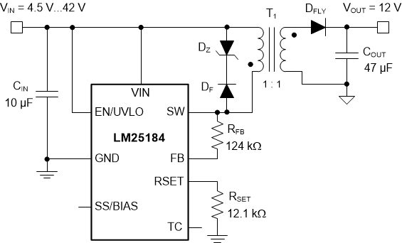
 典型应用
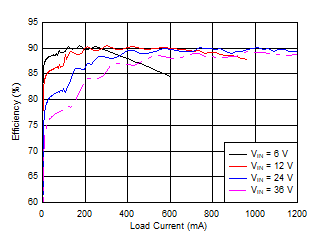
典型应用 典型效率 (VOUT = 12V)