ZHCSEB6 October 2015 DRV8704
PRODUCTION DATA.
- 1 特性
- 2 应用
- 3 说明
- 4 修订历史记录
- 5 Pin Configuration and Functions
- 6 Specifications
-
7 Detailed Description
- 7.1 Overview
- 7.2 Functional Block Diagram
- 7.3 Feature Description
- 7.4 Device Functional Modes
- 7.5
Register Maps
- 7.5.1
Control Registers
- 7.5.1.1 CTRL Register (Address = 0x00h)
- 7.5.1.2 TORQUE Register (Address = 0x01h)
- 7.5.1.3 OFF Register (Address = 0x02h)
- 7.5.1.4 BLANK Register (Address = 0x03h)
- 7.5.1.5 DECAY Register (Address = 0x04h)
- 7.5.1.6 Reserved Register Address = 0x05h
- 7.5.1.7 DRIVE Register Address = 0x06h
- 7.5.1.8 STATUS Register (Address = 0x07h)
- 7.5.1
Control Registers
- 8 Application and Implementation
- 9 Power Supply Recommendations
- 10Layout
- 11器件和文档支持
- 12机械、封装和可订购信息
1 特性
- 脉宽调制 (PWM) 电机驱动器
- 驱动外部 N 沟道金属氧化物半导体场效应晶体管 (MOSFET)
- 双路直流电机的 PWM 控制接口
- 支持 100% 脉宽调制 (PWM) 占空比
- 运行电源电压范围:8V 至 52V
- 可调节栅极驱动(4 级)
- 50mA 至 200mA 拉电流
- 100mA 至 400mA 灌电流
- 集成 PWM 电流调节功能
- 灵活的衰减模式
- 自动混合衰减模式
- 慢速衰减
- 快速衰减
- 混合衰减(百分比可调,快速)
- 高度可配置的串行外设接口 (SPI)
- 以数字方式调节电流的转矩数模转换器 (DAC)
- 低电流休眠模式 (65μA)
- 5V、10mA 低压降 (LDO) 稳压器
- 耐热增强型表面贴装封装
- 38 引脚散热薄型小外形尺寸 (HTSSOP) (PowerPAD) 封装
- 保护特性
- VM 欠压闭锁 (UVLO)
- 栅极驱动器故障 (PDF)
- 过流保护 (OCP)
- 热关断 (TSD)
- 故障条件指示引脚 (nFAULT)
- 通过 SPI 进行故障诊断
空白
2 应用
- 自动取款机和验钞机
- 办公自动化设备
- 工厂自动化和机器人
- 纺织机器
3 说明
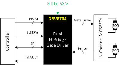
DRV8704 是一款适用于工业设备应用的双路刷式电机控制器。该器件可控制配置为双 H 桥的外部 N 沟道 MOSFET。
该器件使用自适应消隐时间和各种电流衰减模式(包括自动混合衰减模式)对电机电流进行精确控制。
通过一个简单的 PWM 接口即可轻松与控制器电路相连。SPI 串行接口用于对器件的工作模式进行编程。输出电流(转矩)、栅极驱动器设置以及衰减模式均可通过 SPI 串行接口进行编程。
该器件的内部关断功能可提供过流保护、短路保护、栅极驱动器故障排除、欠压锁定 (UVLO) 以及过热保护。FAULTn 引脚用于指示故障情况,故障情况通过各自的 SPI 专用位进行报告。
DRV8704 采用 PowerPAD™带有散热焊盘的 38 引脚 HTSSOP 封装(环保型:符合 RoHS 标准且不含锑/溴)。
器件信息 (1)
| 部件号 | 封装 | 封装尺寸(标称值) |
|---|---|---|
| DRV8704 | HTSSOP (38) | 9.70mm x 4.40mm |
- 要了解所有可用封装,请见数据表末尾的可订购产品附录。
简化电路原理图
