ZHCSOM0 October 2020 DAC43401-Q1 , DAC53401-Q1
PRODUCTION DATA
- 1 特性
- 2 应用
- 3 说明
- 4 Revision History
- 5 Device Comparison Table
- 6 Pin Configuration and Functions
-
7 Specifications
- 7.1 Absolute Maximum Ratings
- 7.2 ESD Ratings
- 7.3 Recommended Operating Conditions
- 7.4 Thermal Information
- 7.5 Electrical Characteristics
- 7.6 Timing Requirements: I2C Standard Mode
- 7.7 Timing Requirements: I2C Fast Mode
- 7.8 Timing Requirements: I2C Fast Mode Plus
- 7.9 Typical Characteristics: VDD = 1.8 V (Reference = VDD) or VDD = 2 V (Internal Reference)
- 7.10 Typical Characteristics: VDD = 5.5 V (Reference = VDD) or VDD = 5 V (Internal Reference)
- 7.11 Typical Characteristics
-
8 Detailed Description
- 8.1 Overview
- 8.2 Functional Block Diagram
- 8.3 Feature Description
- 8.4 Device Functional Modes
- 8.5 Programming
- 8.6
Register Map
- 8.6.1 STATUS Register (address = D0h) [reset = 000Ch or 0014h]
- 8.6.2 GENERAL_CONFIG Register (address = D1h) [reset = 01F0h]
- 8.6.3 TRIGGER Register (address = D3h) [reset = 0008h]
- 8.6.4 DAC_DATA Register (address = 21h) [reset = 0000h]
- 8.6.5 DAC_MARGIN_HIGH Register (address = 25h) [reset = 0000h]
- 8.6.6 DAC_MARGIN_LOW Register (address = 26h) [reset = 0000h]
- 8.6.7 PMBUS_OPERATION Register (address = 01h) [reset = 0000h]
- 8.6.8 PMBUS_STATUS_BYTE Register (address = 78h) [reset = 0000h]
- 8.6.9 PMBUS_VERSION Register (address = 98h) [reset = 2200h]
- 9 Application and Implementation
- 10Power Supply Recommendations
- 11Layout
- 12Device and Documentation Support
- 13Mechanical, Packaging, and Orderable Information
3 说明
10 位 DAC53401-Q1 和 8 位 DAC43401-Q1 (DACx3401-Q1) 是具有引脚兼容性的汽车类缓冲电压输出智能数模转换器 (DAC) 系列产品。这些器件功耗极低且均可采用微型 8 引脚 WSON 封装。凭借这组特性以及微型封装和低功耗,DACx3401-Q1 非常适合以下应用:LED 和通用偏置点生成、电源控制和 PWM 信号生成。
这些器件具有非易失性存储器 (NVM)、一个内部基准和一个兼容 PMBus 的 I2C 接口。DACx3401-Q1 在内部基准或电源基准下运行,提供 1.8V 至 5.5V 的满量程输出。该器件通过 I2C 接口通信。这些器件支持 I2C 标准模式、快速模式和快速+ 模式。
DACx3401-Q1 是智能 DAC 器件,因为它们具有高级集成特性。这些智能 DAC 具有强制检测输出、PWM 输出和 NVM 功能,无需使用软件即可实现系统性能和控制功能。
器件信息
| 器件型号(1) | 封装 | 封装尺寸(标称值) |
|---|---|---|
| DAC53401-Q1 | WSON (8) | 2.00mm × 2.00mm |
| DAC43401-Q1 |
(1) 如需了解所有可用封装,请参阅数据表末尾的封装选项附录。
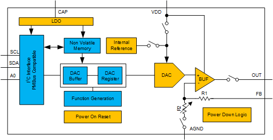
 功能方框图
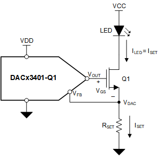
功能方框图 使用 DACx3401-Q1 的 LED 偏置