ZHCSCD9C April   2014  – August 2014 ADC16DX370

PRODUCTION DATA.  

  1. 特性
  2. 应用范围
  3. 说明
  4. 修订历史记录
  5. Pin Configuration and Functions
  6. Specifications
    1. 6.1  Absolute Maximum Ratings
    2. 6.2  Handling Ratings
    3. 6.3  Recommended Operating Conditions
    4. 6.4  Thermal Information
    5. 6.5  Converter Performance Characteristics
    6. 6.6  Power Supply Electrical Characteristics
    7. 6.7  Analog Interface Electrical Characteristics
    8. 6.8  CLKIN, SYSREF, SYNCb Interface Electrical Characteristics
    9. 6.9  Serial Data Output Interface Electrical Characteristics
    10. 6.10 Digital Input Electrical Interface Characteristics
    11. 6.11 Timing Requirements
    12. 6.12 Typical Characteristics
  7. Parameter Measurement Information
    1. 7.1 Over-Range Functional Characteristics
    2. 7.2 Input Clock Divider and Clock Phase Adjustment Functional Characteristics
    3. 7.3 JESD204B Interface Functional Characteristics
  8. Detailed Description
    1. 8.1 Overview
    2. 8.2 Functional Block Diagram
    3. 8.3 Feature Description
      1. 8.3.1  Amplitude and Phase Imbalance Correction of Differential Analog Input
      2. 8.3.2  DC Offset Correction
      3. 8.3.3  Over-Range Detection
      4. 8.3.4  Input Clock Divider
      5. 8.3.5  SYSREF Offset Feature and Detection Gate
      6. 8.3.6  Sampling Instant Phase Adjustment
      7. 8.3.7  Serial Differential Output Drivers
        1. 8.3.7.1 De-Emphasis Equalization
      8. 8.3.8  ADC Core Calibration
      9. 8.3.9  Data Format
      10. 8.3.10 JESD204B Supported Features
      11. 8.3.11 Transport Layer Configuration
        1. 8.3.11.1 Lane Configuration
        2. 8.3.11.2 Frame Format
        3. 8.3.11.3 ILA Information
      12. 8.3.12 Test Pattern Sequences
      13. 8.3.13 JESD204B Link Initialization
      14. 8.3.14 SPI
    4. 8.4 Device Functional Modes
      1. 8.4.1 Power-Down and Sleep Modes
    5. 8.5 Register Map
      1. 8.5.1 Register Descriptions
  9. Application and Implementation
    1. 9.1 Application Information
      1. 9.1.1 Analog Input Considerations
        1. 9.1.1.1 Differential Analog Inputs and Full Scale Range
        2. 9.1.1.2 Analog Input Network Model
        3. 9.1.1.3 Input Bandwidth
        4. 9.1.1.4 Driving the Analog Input
        5. 9.1.1.5 Clipping and Over-Range
      2. 9.1.2 CLKIN, SYSREF, and SYNCb Input Considerations
        1. 9.1.2.1 Driving the CLKIN+ and CLKIN- Input
        2. 9.1.2.2 Clock Noise and Edge Rate
        3. 9.1.2.3 Driving the SYSREF Input
        4. 9.1.2.4 SYSREF Signaling
        5. 9.1.2.5 SYSREF Timing
        6. 9.1.2.6 Effectively Using the SYSREF Offset and Detection Gate Features
        7. 9.1.2.7 Driving the SYNCb Input
      3. 9.1.3 Output Serial Interface Considerations
        1. 9.1.3.1 Output Serial-Lane Interface
        2. 9.1.3.2 Voltage Swing and De-Emphasis Optimization
        3. 9.1.3.3 Minimizing EMI
      4. 9.1.4 JESD204B System Considerations
        1. 9.1.4.1 Frame and LMFC Clock Alignment Procedure
        2. 9.1.4.2 Link Interruption
        3. 9.1.4.3 Synchronization Requests and SYNCb Alignment in Multi-Device Systems
        4. 9.1.4.4 Clock Configuration Examples
        5. 9.1.4.5 Configuring the JESD204B Receiver
      5. 9.1.5 SPI
    2. 9.2 Typical Application
      1. 9.2.1 High-IF Sampling Receiver
        1. 9.2.1.1 Design Requirements
        2. 9.2.1.2 Design Procedure
        3. 9.2.1.3 Application Curve
  10. 10Power Supply Recommendations
    1. 10.1 Power Supply Design
    2. 10.2 Decoupling
  11. 11Layout
    1. 11.1 Layout Guidelines
    2. 11.2 Layout Example
    3. 11.3 Thermal Considerations
  12. 12器件和文档支持
    1. 12.1 器件支持
      1. 12.1.1 技术规格定义
      2. 12.1.2 JESD204B 定义
    2. 12.2 商标
    3. 12.3 静电放电警告
    4. 12.4 Glossary
  13. 13机械、封装和可订购信息

封装选项

机械数据 (封装 | 引脚)
散热焊盘机械数据 (封装 | 引脚)
订购信息

1 特性

  • 分辨率:16 位
  • 转换率:370MSPS
  • 1.7VP-P 输入满量程范围
  • 性能:
    • 输入:150MHz,-3dBFS
      • 信噪比 (SNR):69.6dBFS
      • 噪声频谱密度:-152.3dBFS/Hz
      • 无寄生动态范围 (SFDR):88dBFS
      • 非 HD2 和非 HD-3 寄生信号:-90dBFS
  • 功率耗散:每通道 800mW
  • 缓冲模拟输入
  • 无外部旁路的片上精密基准
  • 支持相位同步的输入采样时钟分频器(1、2、4 或 8 分频)
  • JESD204B 1 子类串行数据接口
    • 信道速率高达 7.4Gb/s
    • 可配置为每通道 1 条或 2 条信道
  • 快速超范围信号
  • 4 线制,1.2V,1.8V,2.5V 或 3V 兼容串行外设接口 (SPI)
  • 56 引脚超薄四方扁平无引线 (WQFN) 封装,(8mm x 8mm,引脚间距 0.5mm)

2 应用范围

  • 高中频 (IF) 采样接收器
  • 多载波基站接收器
    • GSM/EDGE,CDMA2000,UMTS,LTE,WiMax
  • 多样性、多模式和多波段接收器
  • 数字预失真
  • 测试和测量设备
  • 通信仪器仪表
  • 便携式仪表

3 说明

ADC16DX370 器件是一款单片双通道高性能模数转换器,此转换器能够以 370MSPS 的采样速率将模拟输入信号转换为 16 位数字字。 这款转换器使用具有集成输入缓冲器的差分管道式架构,以便在保持低功耗的同时提供出色的动态性能。

集成输入缓冲器消除了来自内部开关电容器采样电路的电荷回馈噪声,并且简化了驱动放大器、抗混叠滤波器以及阻抗匹配的系统级设计。 一个输入采样时钟分频器用可配置相位选择提供整数分频比,以简化系统计时。 集成低噪声电压基准在无需外部去耦合电容器的情况下简化电路板级设计。 在 56 引脚,8mm x 8mm WQFN 封装中,通过一个 JESD204B 1 子类接口提供输出数字数据。 可使用 SPI 来配置与 1.2V 至 3V 逻辑电路兼容的器件。

器件信息(1)

器件型号 封装 封装尺寸(标称值)
ADC16DX370 WQFN (56) 8.00 × 8.00 mm
  1. 要了解所有可用封装,请见数据表末尾的可订购产品附录。

空白

单音频谱,150MHz

ADC16DX370 D016_SNVSA18.gif

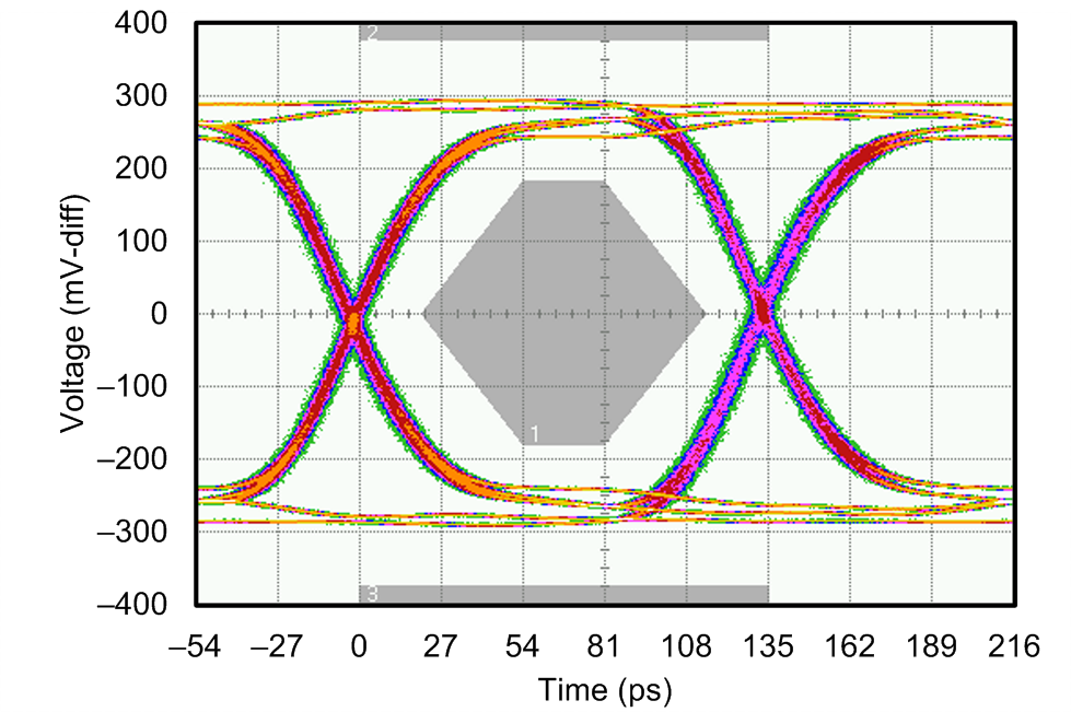
7.4Gb/s 时的输出串行信道眼图

ADC16DX370 eye_mask_7p4G_TX_snvs990.png