SWAU085F July 2011 – January 2022
4 Connection and Firmware Download
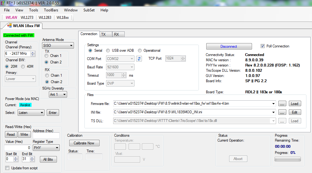
The Connection tab connects the application to a target system-on-chip (SoC) and includes the connection group, which sets the correct port from the available host-PC serial ports as well as the appropriate baud rate (see Figure 4-1).
 Figure 4-1 RT3 Main Working Window After Connection
and Firmware Download
Figure 4-1 RT3 Main Working Window After Connection
and Firmware DownloadTo connect the RTTT application to the SoC, perform the following steps:
- Set the COM port and baud rate fields in the Settings area of the Connection tab.
Note: The default baud rate is 921600 but can be updated to 3M.
- Set the firmware and INI file from the git folder in the Files area of the Connection tab.
- Click the firmware and INI file
path and browse to the location of the file, as shown in Figure 4-2.
 Figure 4-2 Selecting the
Firmware Files to Download
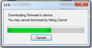
 - Click Load. The RTTT application begins downloading the firmware files entered in the previous steps (see Figure 4-3).
 Figure 4-3 Downloading Firmware Message
 - Click the firmware and INI file
path and browse to the location of the file, as shown in Figure 4-2.
- Select the channel number and frequency from the Channel (Primary) list box in the Channel area.
- Select the channel bandwidth in
the Channel area; click the 20M or 40M button. If the Channel BW is set to
40 MHz, the Primary list box becomes active. Select Upper or Lower channel.
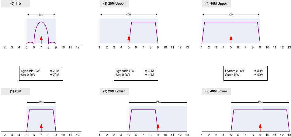
Figure 4-4 shows the packet types for Channel 7. Note: Upper and lower selection is with respect to the primary channel.
 Figure 4-4 Packet Types for Channel 7