SLVA528D September 2012 – August 2021 TPS65381-Q1 , TPS65381A-Q1
- Trademarks
- 1Introduction
- 2Product Overview
- 3Development Process for Management of Systematic Faults
- 4TPS65381x-Q1 Product Architecture for Management of Random Faults
-
5TPS65381x-Q1 Architecture Safety Mechanisms and Assumptions of Use
- 5.1 Power Supply
- 5.2 Regulated Supplies
- 5.3
Diagnostic, Monitoring, and Protection Functions
- 5.3.1 External MCU Fault Detection and Management
- 5.3.2 Voltage Monitor (VMON)
- 5.3.3 Loss-of-Clock Monitor (LCMON)
- 5.3.4 Junction Temperature Monitoring and Current Limiting
- 5.3.5 Analog and Digital MUX (AMUX and DMUX) and Diagnostic Output Pin (DIAG_OUT)
- 5.3.6 Analog Built-In Self-Test (ABIST)
- 5.3.7 Logic Built-In Self-Test (LBIST)
- 5.3.8 Device Configuration Register Protection
- 6Application Diagrams
- 7TPS65381x-Q1 as Safety Element out of Context (SEooC)
- 8Revision History
5.3.3 Loss-of-Clock Monitor (LCMON)
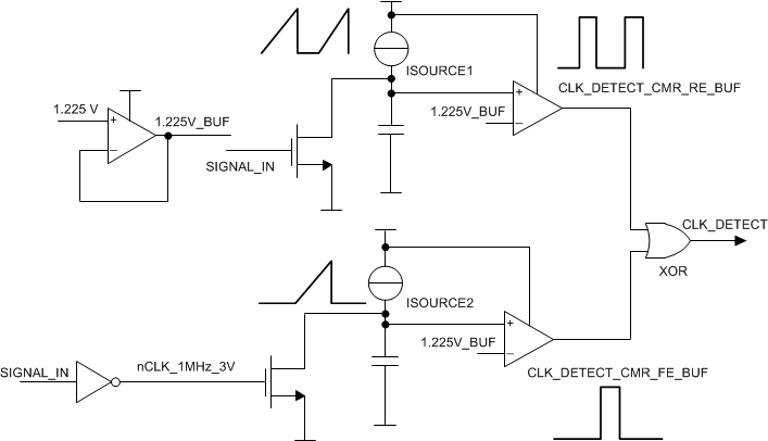
The loss-of-clock monitor (LCMON) detects internal oscillator failures:
- Oscillator clock stuck high or stuck low
- Reduced clock frequency
The LCMON is enabled during a power-up event after a power-on reset is released. The clock monitor remains active during device normal operation (STANDBY, RESET, DIAGNOSTIC, ACTIVE, and SAFE states). In case of a clock failure:
- The device transitions to the STANDBY state.
- All regulators are disabled.
- The digital core is reinitialized
- The reset to the external MCU is asserted low (NRES).
- The failure condition is indicated by the LOCLK bit in the SAFETY_STAT_4 register.
The LCMON has a self-test structure that is activated and monitored by an analog BIST (ABIST). The external MCU can recheck the clock monitor any time when the device is in the DIAGNOSTIC state or the ACTIVE state. The enabled diagnostics emulate a clock failure that causes the LCMON output to toggle. The LCMON toggling pattern is checked by the ABIST, while the external MCU can check that the loss-of-clock status bit is being set during active test. During this self-test, the actual oscillator frequency (4 MHz) is not changed because of this self-test.
 Figure 5-7 Loss-of-Clock Monitor