SLUAAH1 December 2021 UCC24624
1.2.3 UCC24624 Introduction
The UCC24624 is a synchronous rectifier (SR) controller designed especially for high efficiency LLC resonant converter. The UCC24624 SR controller uses drain-to-source voltage (VDS) sensing to determine the SR MOSFET conduction time. When the current starts to flow into the SR body diode, the VDS is the body diode forward voltage drop. The SR MOSFET is turned on when its VDS falls below turn-on threshold(-265mV) longer than turn-on delay. After SR turns on, its voltage drops changes from body diode forward voltage drop into the RDS(ON) voltage drop, and is turned off when VDS rises above the programmable turn-off threshold.
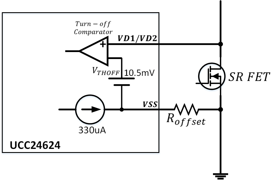
The SR MOSFETs are often turned off early than expect which caused by parasitic inductance. The parasitic inductance can be the contribution from both the trace inductance from the layout and the device package inductance. The designer could optimize the layout to eliminate trace inductance, however package inductance cannot be eliminated. The UCC24624 allows designer to further increase the turn-off threshold to accommodate higher parasitic inductance MOSFET. As shown in Figure 1-2, by connecting a resistor Roffset from VSS pin to the SR MOSFET source, the voltage drop across the external resistor increases the turn-off threshold.
 Figure 1-2 Adjustable Turn-off
Threshold
Figure 1-2 Adjustable Turn-off
ThresholdThe desired turn-off threshold VTHOFF could be calculated as:
Additionally, the UCC24624 also integrated proportional gate drive feature which could further extend MOSFET conduction time. The proportional gate drive reduces the SR MOSFET gate voltage when the SR current is small, and increases its voltage drop. The increased voltage drop could overwhelm the offset voltage introduced by the package inductance. It could bring higher efficiency, due to reduced body diode conduction time. During the proportional gate driver activated region, the SR gate voltage very close to its threshold, and it allows the SR to be turned off fast without considering the time delay from discharging the gate voltage to the threshold voltage.