SLUAAH1 December 2021 UCC24624
2.2 Single SR Controller with Paralleled MOSFETs Configuration
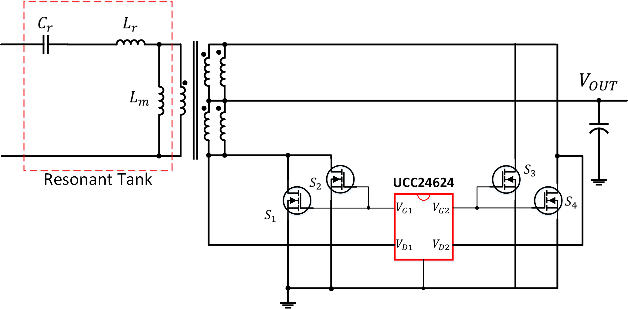
In higher power level applications, a number of MOSFETs can be paralleled to achieve lower on-state resistance and reduce conduction loss as shown in Figure 2-2. Also, the RDS(ON) has a positive temperature coefficient so the FETs will automatically share current, facilitating optimal thermal distribution among the SR devices. This improves the thermal management.
 Figure 2-2 Single UCC24624 with Parallel MOSFETs Application Schematic
To minimize the size of the converter and decrease output ripple voltage for low-voltage applications, designers often increase the switching frequency to reduce the size of the output inductor and capacitor. If multiple FETs are in parallel, increased switching frequency increases the gate drive losses which might make UCC24624 overheat. According to Equation 9, the gate driver losses greatly increases as shown in Equation 11.