SLUAA69 July 2020 – MONTH TPS548D22
6.3 Startup Waveforms and Behaviors Analysis at the First OVP
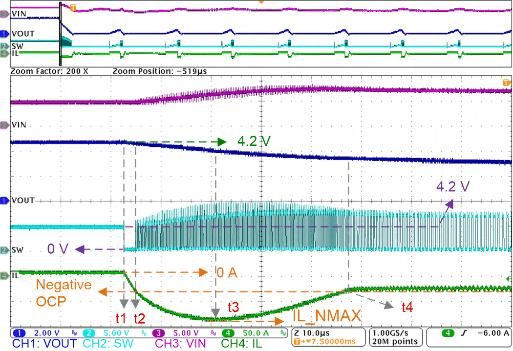
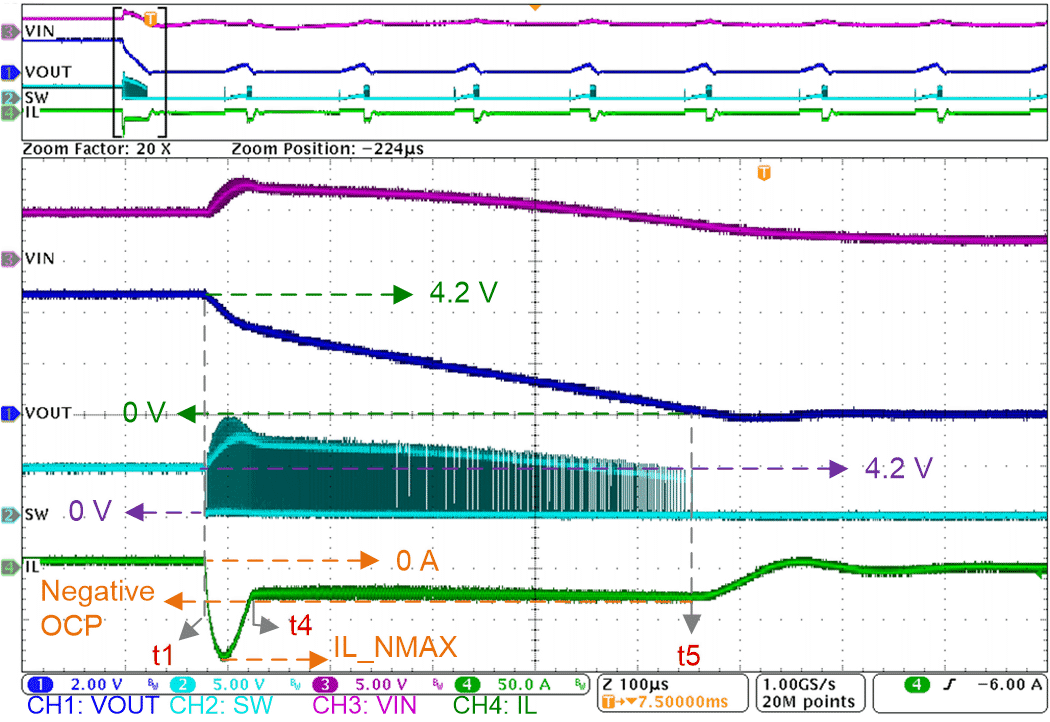
Figure 6-4 and Figure 6-5 show waveforms at the first OVP with details.
 Figure 6-4 Start-up Waveforms at the First OVP
with Details: 1
 Figure 6-5 Start-up Waveforms at the First OVP
with Details: 2
Figure 6-5 Start-up Waveforms at the First OVP
with Details: 2At t2, normally, the device is supposed to turn on the high-side MOSFET for a minimum on-time to limit the inductor current exceeding the negative OCP level to protect the low-side MOSFET during OVP discharge. But from t2 to t3, it looks like that inductor current exceeds the negative OCP level and increases in the negative direction. In the negative direction, the rising speed of the inductor current is faster than the falling speed. The difference gradually becomes smaller and smaller with output discharging. During the minimum on-time of the high-side MOSFET, inductor current falls in the negative direction. During the on-time of the low-side MOSFET, inductor current increases for at least a minimum on-time in the negative direction. As a result, the increment is larger than the decrement and the inductor current increases in the negative direction. The large inductor current could exceed the inductor saturation current and damage the MOSFETs.
At t3, in the negative direction, the rising speed of inductor current becomes equal to the falling speed. From t3 to t4, the rising speed of inductor current is slower than the falling speed and the difference gradually increases with the output continuously discharging. Inductor current decreases in the negative direction and finally goes back to the negative OCP level at t4.
From t4 to t5, the high-side MOSFET continuously turns on for a minimum on-time until the output voltage is close to being completely discharged at t5. In this period, negative OCP is cyclically triggered. More details about OCP behaviors are in the next section.