SLUAA69 July   2020  – MONTH  TPS548D22


  1.   Trademarks
  2. 1Introduction
    1. 1.1 LED Driver Methods
    2. 1.2 Power Supply Solutions for Common-Cathode LED Display
  3. 2Principle of Synchronous Buck with Sinking Current Application
  4. 3 Design Considerations and Analysis
    1. 3.1 Choose an IC with Sufficient Current Sinking
    2. 3.2 Choose IC Supporting Negative OCP
    3. 3.3 Choose an IC Supporting Pre-Bias Startup
    4. 3.4 Analysis of System Startup
  5. 4 TI Devices and Functionalities
    1. 4.1 Negative OCP Functionality
    2. 4.2 Hiccup Mode and Latch-off Mode
    3. 4.3 UVP and OVP Functionality
  6. 5 TI Solution
  7. 6 Bench Test and Result
    1. 6.1 Bench Test Configuration
    2. 6.2 Startup Waveforms and Behaviors Analysis Overview
    3. 6.3 Startup Waveforms and Behaviors Analysis at the First OVP
    4. 6.4 Startup Waveforms and Behaviors Analysis after the First OVP
    5. 6.5 Waveforms and Behaviors Analysis of Startup Solution with Lazy Loading
  8. 7 Conclusion
  9. 8References

TI Solution

Taking 220 W power supply with hiccup mode as an example, the buck converter is designed for 1-V 30-A output at 4.2-V input. For the component parameters design, it was shown in Principle of Synchronous Buck with Sinking Current Application that sourcing current and sinking current use of a synchronous buck converter have the same power stage (except for the input capacitor), as well as design methods and formulas. Fortunately, TPS548D22EVM-784 provides a fixed 1-V output at up to 40 A from a 12-V input bus. It is possible to use it to verify this common-anode power solution with just some minor changes as shown in Figure 5-1.

The first change is the VDD supply voltage. Note that the VDD UVLO rising threshold of TPS548D22 is typically 4.25 V. With 4.2-V input connecting to VDD, the device will be in UVLO state and cannot start. A boost circuit or an external power supply of 12 V should be used to make sure the device is properly powered and enabled. The second change is the resistor divider network of reference voltage. The EVM is set in latch-off mode. So, Rsel (R23 in EVM) should be changed to 33.2 kΩ for hiccup mode. The hiccup time is 16 ms (with 1 ms soft-start option).
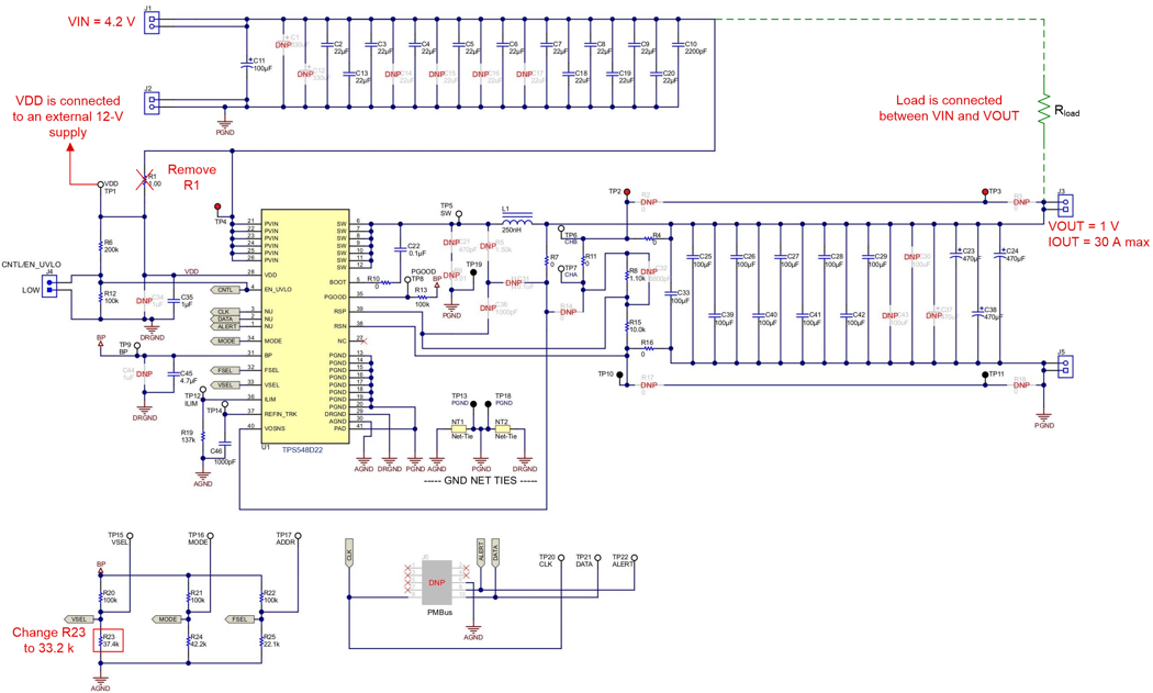
GUID-20200604-SS0I-N91M-VHWF-5K2XF6FB0KZV-low.png Figure 5-1 Schematic of TPS548D22 with Sinking Current Application
A question is left in Analysis of System Start Up - how does one ensure that the converter does not get stuck during the start-up state? Since a small load resistance will charge the output capacitor quickly, causing an OVP to occur, one approach is to start up with a light load that slows down the charging speed of the output capacitor. Then the OVP may not be triggered after the device is enabled and the device could start up from a pre-bias condition. Or a simpler approach is to start up with no load. With no load condition, the path charging the output capacitor through the load resistor does not exist anymore. Then the device can start up normally and an OVP event will not occur. Once the start-up is finished, the PGOOD signal could be used as an enable signal to add the load. Finally, the synchronous buck converter with sinking current can work fine in steady state, as well as in transient conditions.

Bench Test and Result analyzes start-up behaviors of this synchronous buck converter with sinking current application based on bench test waveforms. Also, a lazy loading solution, which means to start up with no load and then add the load after start up is complete, will be analyzed.