SLAU150A December 2004 – October 2021 ADS7881 , ADS7891
1.2.1 Signal Conditioning
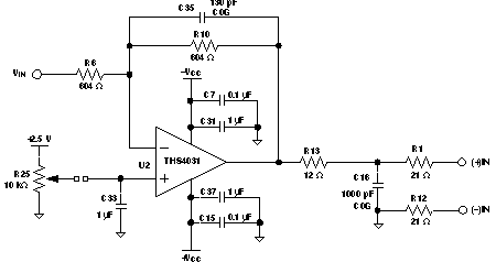
The factory recommends the analog input to any SAR-type converter be buffered and low-pass filtered. The input buffer on the ADS78x1EVM uses the THS4031 (as shown in Figure 1-1) configured as an inverting gain of one. However, the amplifier is not stable at a gain of one, and is thus configured for inverting gain of one. The THS4031 was selected for its low noise, high slew rate, and fast settling time. The low-pass filter resistor and capacitor values were selected such that the ADS78x1EVM meets the 1-MHz AC performance specifications listed in the data sheet. The series resistor works in conjunction with the capacitor to filter the input signal, but also isolates the amplifier from the capacitive load. The capacitor to ground at the input of the ADC works in conjunction with the series resistor to filter the input signal, and functions as a charge reservoir. This external filter capacitor works with the amplifier to charge the internal sampling capacitor during sampling mode. Resistors R1 and R12 were selected to reduce offset.
The EVM has a provision to offset the input voltage by adjusting R25, a 10-kΩ potentiometer.
 Figure 1-1 ADS7881 Input Buffer Circuit