ZHCS971B June 2012 – July 2016 TS3USB3200
PRODUCTION DATA.
7 Detailed Description
7.1 Overview
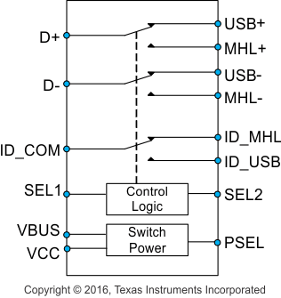
The TS3USB3200 supports high-speed Mobile High-Definition Link (MHL) or Mobility Display Port (MyDP) switching, as well as USB 2.0 High-Speed (480 Mbps) switching in the same package. An additional integrated ID switch is also included to support USB/MHL or MyDP ID for easy information control. These configurations allow the system designer to use a common USB or Mico-USB connector to support both MHL/MyDP video signals and USB data.
7.2 Functional Block Diagram

7.3 Feature Description
7.3.1 Flexible Power Control
Device can be powered by VBUS or by VCC. This allows the device to run off a 4.3-V battery voltage or 5 V from an external USB device. If both a battery and external USB device are supplying voltage on the VCC and VBUS pins the PSEL can be used to select which power supply is used to save battery power.
7.3.2 IOFF Protection Prevents Current Leakage in Powered Down State (VCC and VBUS= 0 V)
When there is no power supplied to the IC, all of the I/O signal paths are placed in a high impedance state, which isolates the data paths when they are not being used.
7.3.3 1.8-V Compatible Control Inputs (SEL1, SEL2, and PSEL)
The TS3USB3200 logic control input pins can operate with 1.8-V logic since the VIH minimum for the SEL1, SEL2, and PSEL is 1.3 V.
7.4 Device Functional Modes
The TS3USB32000 device can select which power supply pin VCC or VBUS will power the device when voltages are present on both pins.
Table 1. Function Table (Power Source)
| VCC | VBUS | PSEL(1) | POWER SOURCE |
|---|---|---|---|
| L | L | X | No Power. All I/O in High-Z |
| L | H | X | VBUS |
| H | L | X | VCC |
| H | H | L | VCC |
| H | H | H | VBUS |
Table 2. Function Table (Signal and ID Select)
| SEL1(1) | SEL2(1) | CONNECTION | High-Z |
|---|---|---|---|
| L | L | D+/D– to USB+/USB–, ID_COM to ID_USB | MHL+/MHL–, ID_MHL |
| L | H | D+/D– to USB+/USB–, ID_COM to ID_MHL | MHL+/MHL–, ID_USB |
| H | L | D+/D– to MHL+/MHL–, ID_COM to ID_USB | USB+/USB–, ID_MHL |
| H | H | D+/D– to MHL+/MHL–, ID_COM to ID_MHL | USB+/USB–, ID_USB |