ZHCSB59E April 2011 – December 2015 TPS22924B , TPS22924C
PRODUCTION DATA.
- 1 特性
- 2 应用
- 3 说明
- 4 修订历史记录
- 5 Device Comparison Table
- 6 Pin Configuration and Functions
-
7 Specifications
- 7.1 Absolute Maximum Ratings
- 7.2 ESD Ratings
- 7.3 Recommended Operating Conditions
- 7.4 Thermal Information
- 7.5 Electrical Characteristics
- 7.6 Switching Characteristics, VIN = 3.6 V
- 7.7 Switching Characteristics, VIN = 0.9 V
- 7.8 Typical Characteristics
- 7.9 AC Characteristics (TPS22924B)
- 7.10 AC Characteristics (TPS22924C)
- 8 Parameter Measurement Information
- 9 Detailed Description
- 10Application and Implementation
- 11Power Supply Recommendations
- 12Layout
- 13器件和文档支持
- 14机械、封装和可订购信息
封装选项
机械数据 (封装 | 引脚)
散热焊盘机械数据 (封装 | 引脚)
订购信息
10 Application and Implementation
NOTE
Information in the following applications sections is not part of the TI component specification, and TI does not warrant its accuracy or completeness. TI’s customers are responsible for determining suitability of components for their purposes. Customers should validate and test their design implementation to confirm system functionality.
10.1 Application Information
10.1.1 VIN to VOUT Voltage Drop
The VIN to VOUT voltage drop in the device is determined by the RON of the device and the load current. The RON of the device depends upon the VIN condition of the device. Refer to the RON specification of the device in the Electrical Characteristics table of this datasheet. Once the RON of the device is determined based upon the VIN conditions, use Equation 1 to calculate the VIN to VOUT voltage drop:
where
- ΔV = Voltage drop from VIN to VOUT
- ILOAD = Load current
- RON = On-resistance of the device for a specific VIN
- An appropriate ILOAD must be chosen such that the IMAX specification of the device is not violated.
10.1.2 Input Capacitor
To limit the voltage drop on the input supply caused by transient inrush currents, when the switch turns on into a discharged load capacitor or short-circuit, a capacitor needs to be placed between VIN and GND. A 1-μF ceramic capacitor, CIN, placed close to the pins is usually sufficient. Higher values of CIN can be used to further reduce the voltage drop.
10.1.3 Output Capacitor
A CIN to CL ratio of 10 to 1 is recommended for minimizing VIN dip caused by inrush currents during startup.
10.2 Typical Application
 Figure 43. Typical Application
10.2.1 Design Requirements
| DESIGN PARAMETER | EXAMPLE VALUE |
|---|---|
| VIN | 3.6 V |
| CL | 1 µF |
| Maximum Acceptable Inrush Current | 40 mA |
10.2.2 Detailed Design Procedure
10.2.2.1 Managing Inrush Current
When the switch is enabled, the output capacitors must be charged up from 0-V to VIN. This charge arrives in the form of inrush current. Inrush current can be calculated using the following equation:

where
- C = Output capacitance
-
 = Output slew rate
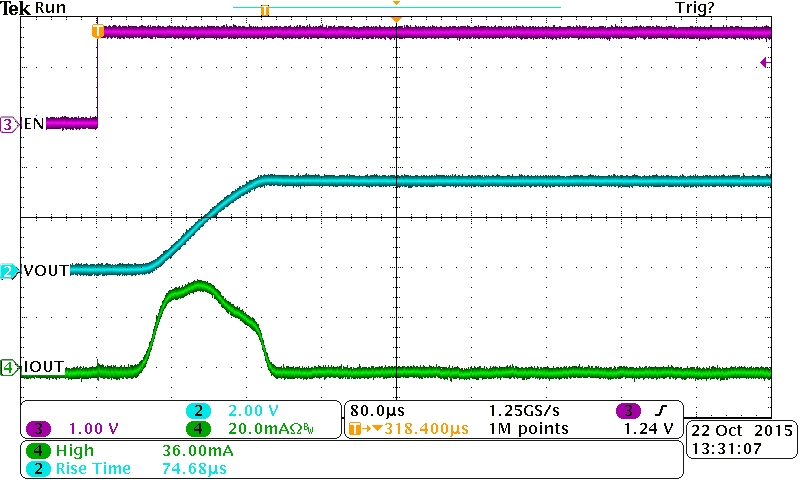
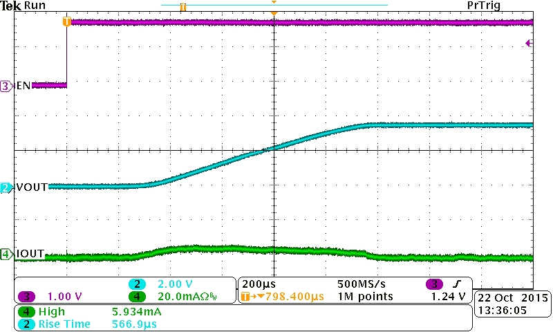
The TPS22924B offers a very slow controlled rise time for minimizing inrush current. This device can be selected based upon the maximum acceptable slew rate which can be calculated using the design requirements and the inrush current equation. An output capacitance of 1.0 μF will be used since the amount of inrush increases with output capacitance:


To ensure an inrush current of less than 40 mA, a device with a slew rate less than 40 V/ms must be used.
The TPS22924B has a typical rise time of 96 μs at 3.6 V. This results in a slew rate of 37.5 V/ms which meets the above design requirements. For an even lower inrush current requirement, the TPS22924C can be used. The slower rise time of 800 μs at 3.6V results in a slew rate of 4.5 V/ms, well below the design requirements.

