SLLSE81A March 2011 – March 2016 SN75LVCP600S
PRODUCTION DATA.
- 1 Features
- 2 Applications
- 3 Description
- 4 Revision History
- 5 Pin Configuration and Functions
- 6 Specifications
- 7 Parameter Measurement Information
- 8 Detailed Description
- 9 Application and Implementation
- 10Power Supply Recommendations
- 11Layout
- 12Device and Documentation Support
- 13Mechanical, Packaging, and Orderable Information
9 Application and Implementation
NOTE
Information in the following applications sections is not part of the TI component specification, and TI does not warrant its accuracy or completeness. TI’s customers are responsible for determining suitability of components for their purposes. Customers should validate and test their design implementation to confirm system functionality.
9.1 Application Information
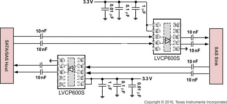
The SN75LVCP600S is a single-channel SATA/SAS redriver and signal conditioner supporting data rates up to 6 Gbps. The inputs incorporate an OOB (out-of-band) detector, which automatically squelches the output while maintaining a stable common-mode voltage compliant to the SATA/SAS link. This device is designed for applications where an extended temperature range is required.
9.2 Typical Application
 Figure 13. Typical Application
9.2.1 Design Requirements
For this design example, use the values shown in Table 2.
Table 2. Design Parameters
| PARAMETER | VALUE |
|---|---|
| VCC | 3.3 V |
| ICC | 32 mA |
| Input voltage | 275 mVpp to 1.6 Vpp |
| Output voltage | 385 mVpp to 1.3 Vpp |
9.2.2 Detailed Design Procedure
- Determine the loss profile between Host and HDD.
- Based upon loss profile and signal swing, determine the optimal equalization setting EQ pin.
- Select appropriate de-emphasis with DE control pin.
- Depending on loss profile, select squelch threshold using SQ_TH.
- For low level, use 47-kΩ pulldown. For high level, tie pin to VCC.
9.2.3 Application Curves
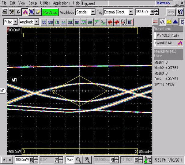
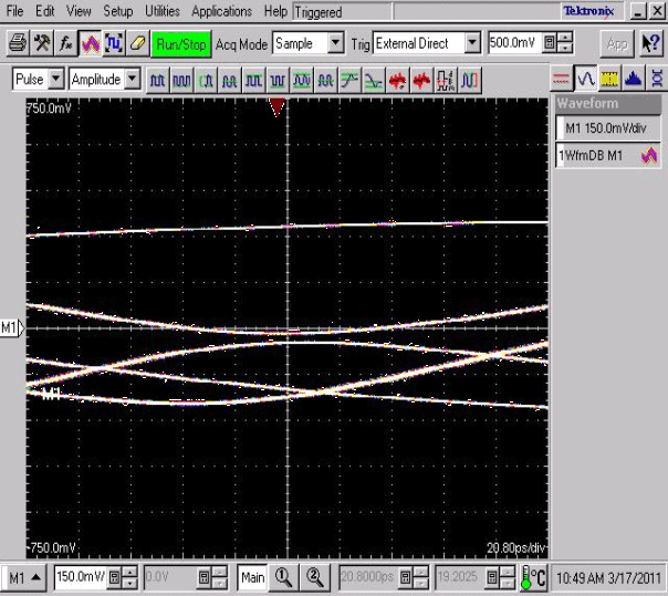
| MODE = 0 |
Input of LVCP600S
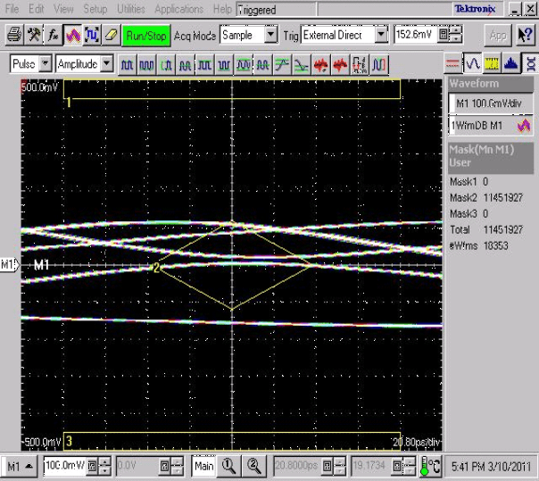
| MODE = 0 |
Input of LVCP600S
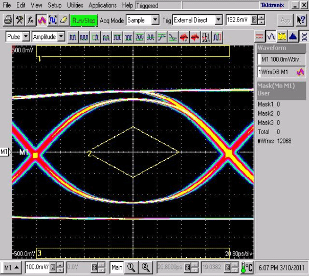
| MODE = 0 |
Output = 2 Inches (5.1 cm) After Equalizing
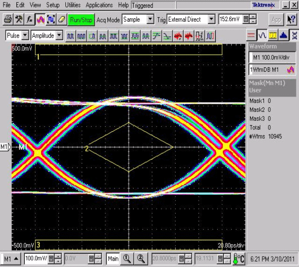
| MODE = 0 |
Output = 2 Inches (5.1 cm) After Equalizing
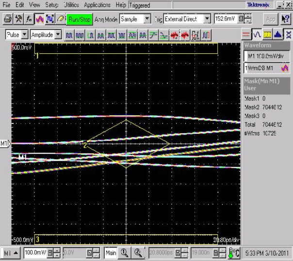
| MODE = 0 |
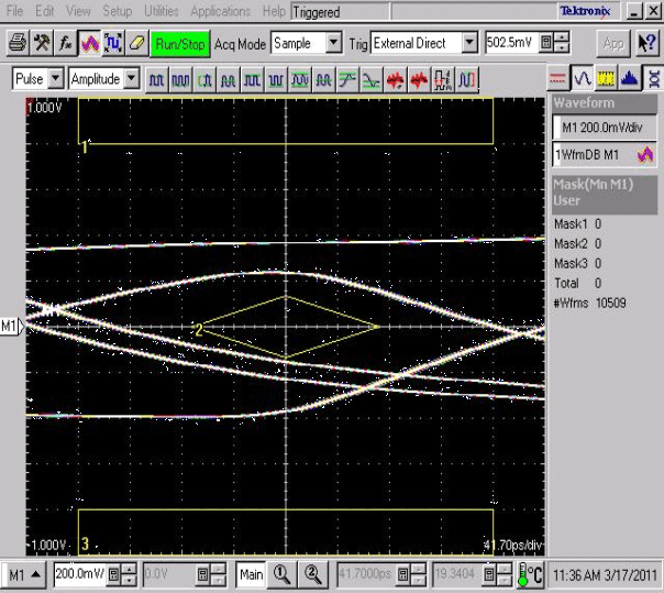
| MODE = 1 |
| MODE = 1 |
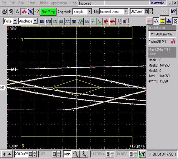
| MODE = 1 |
Input of LVCP600S
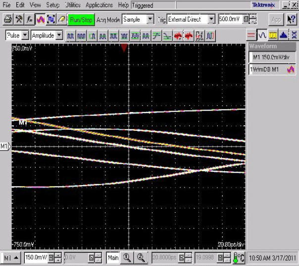
| MODE = 1 |
Input of LVCP600S
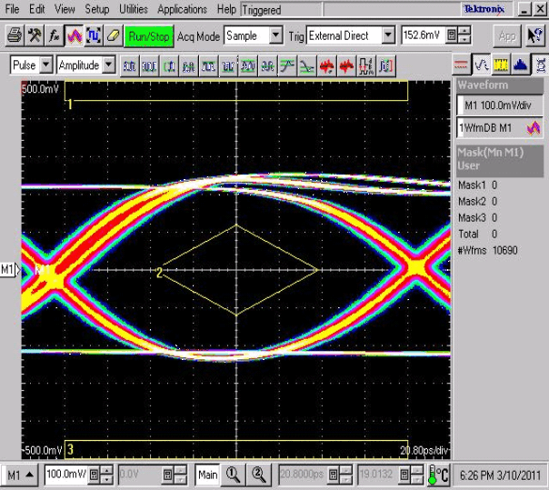
| MODE = 0 |
Output = 2 Inches (5.1 cm) After Equalizing
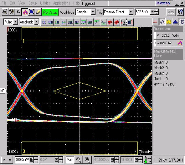
| MODE = 1 |
Output = 2 Inches (5.1 cm) After Equalizing
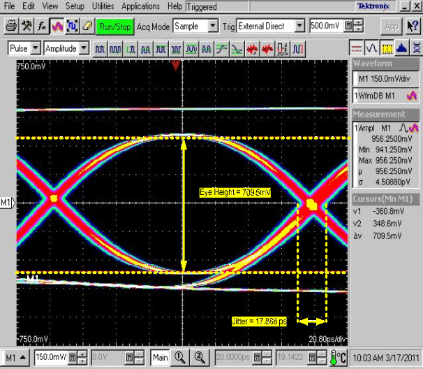
| MODE = 1 |
Output = 2 Inches) After Equalizing
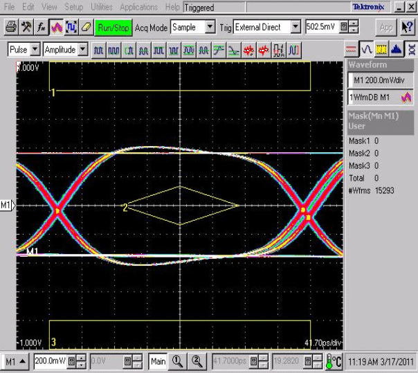
| MODE = 1 |
Output = 2 Inches (5.1 cm) After Equalizing
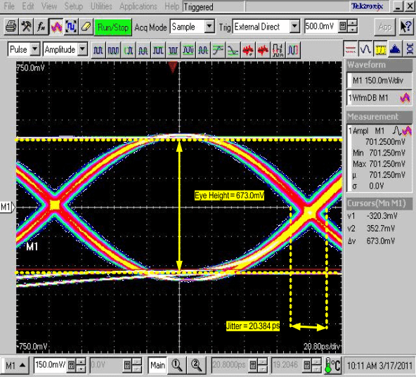
| MODE = 1 |
Output = 2 Inches (5.1 cm) after Equalizing
9.3 System Examples
