SNVS454E August 2006 – December 2014 LM2830 , LM2830-Q1
PRODUCTION DATA.
- 1 Features
- 2 Applications
- 3 Description
- 4 Revision History
- 5 Pin Configuration and Functions
- 6 Specifications
- 7 Detailed Description
-
8 Application and Implementation
- 8.1 Application Information
- 8.2
Typical Applications
- 8.2.1 LM2830X Design Vo = 1.2 V at 1.0A
- 8.2.2 LM2830X Design Vo = 0.6 V at 1.0-A
- 8.2.3 LM2830X Design Vo = 3.3 V at 1.0-A
- 8.2.4 LM2830Z Design Vo = 3.3 V at 1.0-A
- 8.2.5 LM2830Z Design Vo = 1.2 V at 1.0-A
- 8.2.6 LM2830X Dual Converters With Delayed Enabled Design
- 8.2.7 LM2830X Buck Converter and Voltage Double Circuit With LDO Follower
- 9 Power Supply Recommendations
- 10Layout
- 11Device and Documentation Support
- 12Mechanical, Packaging, and Orderable Information
10 Layout
10.1 Layout Guidelines
When planning layout there are a few things to consider when trying to achieve a clean, regulated output. The most important consideration is the close coupling of the GND connections of the input capacitor and the catch diode D1. These ground ends should be close to one another and be connected to the GND plane with at least two through-holes. Place these components as close to the IC as possible. Next in importance is the location of the GND connection of the output capacitor, which should be near the GND connections of CIN and D1.
There should be a continuous ground plane on the bottom layer of a two-layer board except under the switching node island.
The FB pin is a high-impedance node and care should be taken to make the FB trace short to avoid noise pickup and inaccurate regulation. The feedback resistors should be placed as close as possible to the IC, with the GND of R1 placed as close as possible to the GND of the IC. The VOUT trace to R2 should be routed away from the inductor and any other traces that are switching.
High AC currents flow through the VIN, SW and VOUT traces, so they should be as short and wide as possible. However, making the traces wide increases radiated noise, so the designer must make this trade-off. Radiated noise can be decreased by choosing a shielded inductor.
The remaining components should also be placed as close as possible to the IC. See Application Note AN-1229 SNVA054 for further considerations and the LM2830 demo board as an example of a four-layer layout.
10.2 Layout Example
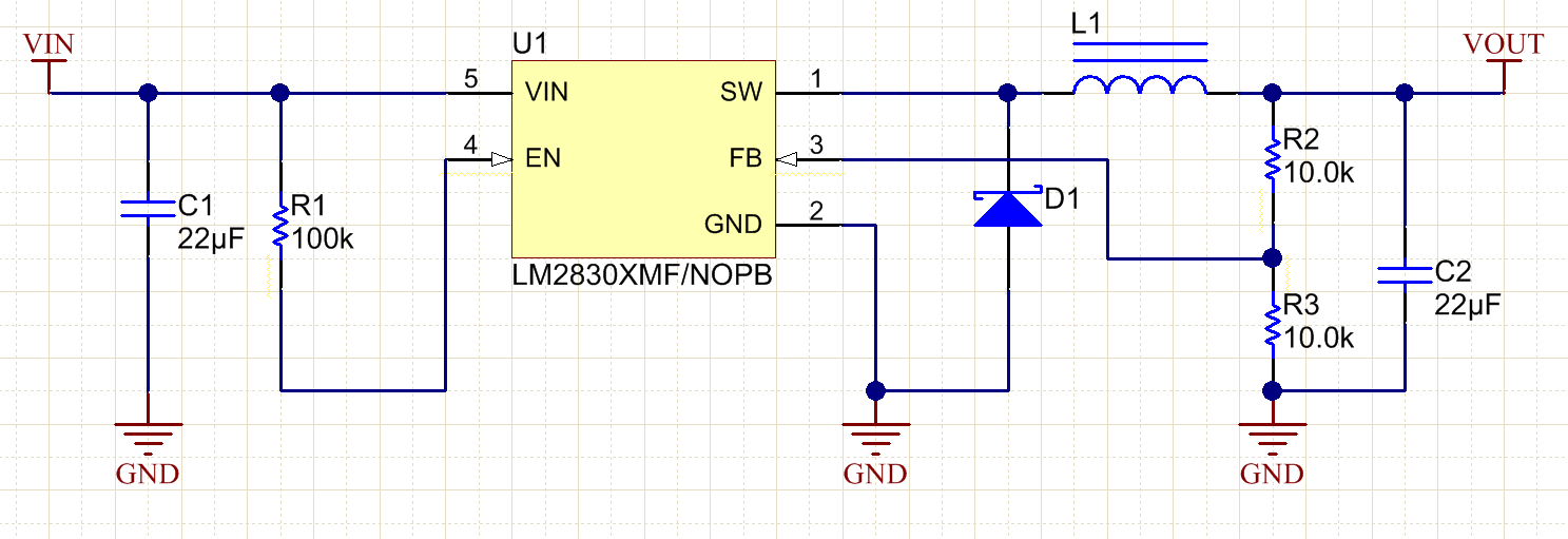 Figure 29. Example Schematic
 Figure 30. PCB Layout Example
10.3 Thermal Considerations
The PCB size, weight of copper used to route traces and ground plane, and number of layers within the PCB can greatly effect RθJA. The type and number of thermal vias can also make a large difference in the thermal impedance. Thermal vias are necessary in most applications. They conduct heat from the surface of the PCB to the ground plane. Four to six thermal vias should be placed under the exposed pad to the ground plane if the WSON package is used.
Thermal impedance also depends on the thermal properties of the application operating conditions (Vin, Vo, Io etc), and the surrounding circuitry.
Silicon Junction Temperature Determination Method 1:
To accurately measure the silicon temperature for a given application, two methods can be used. The first method requires the user to know the thermal impedance of the silicon junction to top case temperature.
Some clarification needs to be made before we go any further.
RθJC is the thermal impedance from all six sides of an IC package to silicon junction.
RΦJC is the thermal impedance from top case to the silicon junction.
In this data sheet we will use RΦJC so that it allows the user to measure top case temperature with a small thermocouple attached to the top case.
RΦJC is approximately 30°C/Watt for the 6-pin WSON package with the exposed pad. Knowing the internal dissipation from the efficiency calculation given previously, and the case temperature, which can be empirically measured on the bench we have:

Therefore:
From the previous example:
The second method can give a very accurate silicon junction temperature.
The first step is to determine RθJA of the application. The LM2830 device has over-temperature protection circuitry. When the silicon temperature reaches 165°C, the device stops switching. The protection circuitry has a hysteresis of about 15°C. Once the silicon temperature has decreased to approximately 150°C, the device will start to switch again. Knowing this, the RθJA for any application can be characterized during the early stages of the design one may calculate the RθJA by placing the PCB circuit into a thermal chamber. Raise the ambient temperature in the given working application until the circuit enters thermal shutdown. If the SW-pin is monitored, it will be obvious when the internal PFET stops switching, indicating a junction temperature of 165°C. Knowing the internal power dissipation from the above methods, the junction temperature, and the ambient temperature RθJA can be determined.

Once this is determined, the maximum ambient temperature allowed for a desired junction temperature can be found.
An example of calculating RθJA for an application using the Texas Instruments LM2830 WSON demonstration board is shown below.
The four layer PCB is constructed using FR4 with ½ oz copper traces. The copper ground plane is on the bottom layer. The ground plane is accessed by two vias. The board measures 3-cm × 3-cm. It was placed in an oven with no forced airflow. The ambient temperature was raised to 144°C, and at that temperature, the device went into thermal shutdown.
From the previous example:
If the junction temperature was to be kept below 125°C, then the ambient temperature could not go above 109°C
10.4 WSON Package
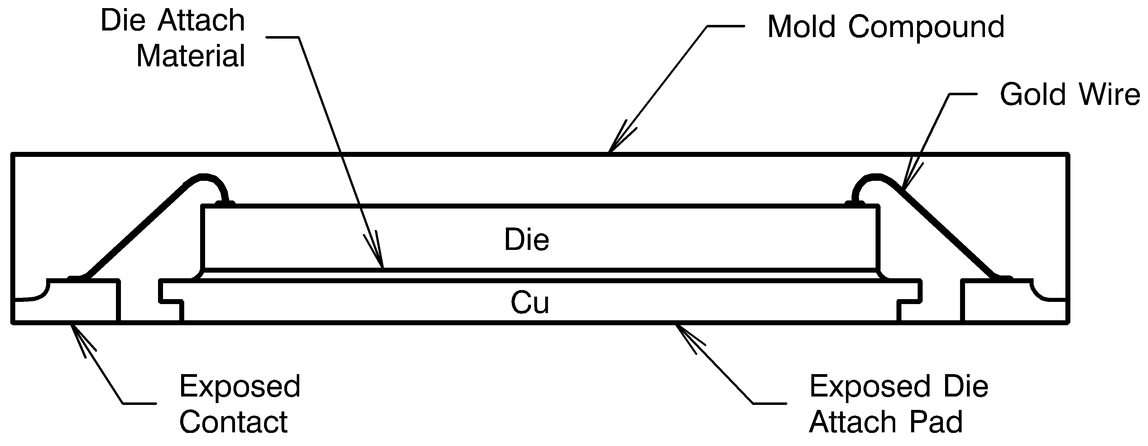 Figure 31. Internal WSON Connection
For certain high-power applications, the PCB land may be modified to a "dog bone" shape (see Figure 32). By increasing the size of ground plane, and adding thermal vias, the RθJA for the application can be reduced.
 Figure 32. 6-Lead WSON PCB "Dog Bone" Layout