ZHCSDT0C june 2015 – may 2023 ISO5851
PRODUCTION DATA
- 1
- 1 特性
- 2 应用
- 3 说明
- 4 Revision History
- 5 说明(续)
- 6 Pin Configuration and Function
-
7 Specifications
- 7.1 Absolute Maximum Ratings
- 7.2 ESD Ratings
- 7.3 Recommended Operating Conditions
- 7.4 Thermal Information
- 7.5 Power Ratings
- 7.6 Insulation Characteristics
- 7.7 Safety-Related Certifications
- 7.8 Safety Limiting Values
- 7.9 Electrical Characteristics
- 7.10 Switching Characteristics
- 7.11 Insulation Characteristics Curves
- 7.12 Typical Characteristics
- 8 Parameter Measurement Information
- 9 Detailed Description
-
10Application and Implementation
- 10.1 Application Information
- 10.2
Typical Applications
- 10.2.1 Design Requirements
- 10.2.2
Detailed Design Procedure
- 10.2.2.1 Recommended ISO5851 Application Circuit
- 10.2.2.2 FLT and RDY Pin Circuitry
- 10.2.2.3 Driving the Control Inputs
- 10.2.2.4 Local Shutdown and Reset
- 10.2.2.5 Global-Shutdown and Reset
- 10.2.2.6 Auto-Reset
- 10.2.2.7 DESAT Pin Protection
- 10.2.2.8 DESAT Diode and DESAT Threshold
- 10.2.2.9 Determining the Maximum Available, Dynamic Output Power, POD-max
- 10.2.2.10 Example
- 10.2.2.11 Higher Output Current Using an External Current Buffer
- 10.2.3 Application Curves
- 11Power Supply Recommendations
- 12Layout
- 13Device and Documentation Support
- 14Mechanical, Packaging, and Orderable Information
3 说明
ISO5851 是一款用于 IGBT 和 MOSFET 的 5.7 kVRMS 增强型隔离栅极驱动器,具有 2.5A 的拉电流能力和 5A 的灌电流能力。输入端由 3V 至 5.5V 的单电源供电运行。输出侧支持的电源电压范围为 15V 至 30V。两路互补 CMOS 输入控制栅极驱动器输出状态。76ns 的短暂传播时间保证了对于输出级的精确控制。
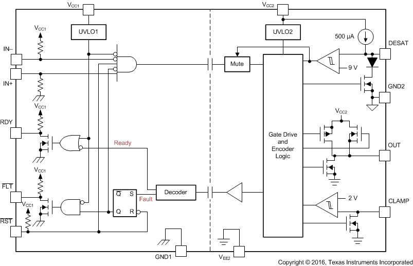
内置的去饱和 (DESAT) 故障检测功能可识别 IGBT 何时处于过载状态。当检测到 DESAT 时,栅极驱动器输出会被拉低为 VEE2 电势,从而将 IGBT 立即关断。
当发生去饱和故障时,器件会通过隔离隔栅发送故障信号,以将输入端的 FLT 输出拉为低电平并阻断隔离器的输入。FLT 的输出状态将被锁存,可通过 RST 输入上的低电平有效脉冲复位。
器件信息(1)
| 器件型号 | 封装 | 封装尺寸(标称值) |
|---|---|---|
| ISO5851 | SOIC (16) | 10.30mm x 7.50mm |
(1) 要了解所有可用封装,请见数据表末尾的可订购产品附录。
 功能方框图
功能方框图