ZHCS597B December 2011 – May 2015 DAC1282
PRODUCTION DATA.
- 1 特性
- 2 应用
- 3 说明
- 4 修订历史记录
- 5 Device Comparison
- 6 Pin Configuration and Functions
- 7 Specifications
-
8 Detailed Description
- 8.1 Overview
- 8.2
Feature Description
- 8.2.1 Signal Output (VOUTP, VOUTN)
- 8.2.2 DAC Modes
- 8.2.3 Reference Voltage (VREF)
- 8.2.4 Output Filter (CAPP, CAPN)
- 8.2.5 Output Switch (SWINP, SWINN, SWOUTP, SWOUTN)
- 8.2.6 Clock Input (CLK)
- 8.2.7 Switch Control/External Digital Input (SW/TD)
- 8.2.8 SYNC
- 8.2.9 RESET/PWDN
- 8.2.10 AVDD, AVSS, and DVDD Power Supplies
- 8.2.11 Step Response
- 8.2.12 Frequency Response
- 8.3 Device Functional Modes
- 8.4 Programming
- 8.5 Register Map
- 9 Application and Implementation
- 10器件和文档支持
- 11机械、封装和可订购信息
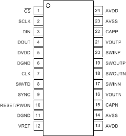
6 Pin Configuration and Functions
PW Package
24-Pin TSSOP
Top VIew

Pin Functions
| PIN | FUNCTION | DESCRIPTION | |
|---|---|---|---|
| NAME | NO. | ||
| AVDD | 13, 24 | Analog supply | Analog positive power supply |
| AVSS | 14 | Analog supply | Analog negative power supply, reference ground |
| AVSS | 23 | Analog supply | Analog negative power supply |
| CAPN | 15 | Analog | External capacitor connected to VOUTN |
| CAPP | 22 | Analog | External capacitor connected to VOUTP |
| CS | 1 | Digital input | Serial port chip select |
| CLK | 7 | Digital input | Master clock 4.096 MHz |
| DGND | 6 | Ground | Key digital ground |
| DGND | 11 | Ground | Digital ground |
| DIN | 3 | Digital input | Serial port data input |
| DOUT | 4 | Digital output | Serial port data output |
| DVDD | 5 | Digital supply | Digital power supply: 1.65 V to 3.6 V |
| RESET/PWDN | 10 | Digital input | Reset/power-down input |
| SCLK | 2 | Digital input | Serial port shift clock |
| SW/TD | 8 | Digital input | Switch control input or bitstream input |
| SWINN | 17 | Analog I/O | Switch negative input |
| SWINP | 20 | Analog I/O | Switch positive input |
| SWOUTN | 18 | Analog I/O | Switch negative output |
| SWOUTP | 19 | Analog I/O | Switch positive output |
| SYNC | 9 | Digital input | Synchronize input |
| VOUTN | 16 | Analog output | Negative voltage output |
| VOUTP | 21 | Analog output | Positive voltage output |
| VREF | 12 | Analog input | Reference voltage input |