LMT70 是一款带有输出使能引脚的超小型、高精度、低功耗互补金属氧化物半导体 (CMOS) 模拟温度传感器。 LMT70 几乎适用于所有高精度、低功耗的经济高效型温度感测应用,例如物联网 (IoT) 传感器节点、医疗温度计、高精度仪器仪表和电池供电设备。 LMT70 也是 RTD 和高精度 NTC/PTC 热敏电阻的理想替代产品。
多个 LMT70 可利用输出使能引脚来共用一个模数转换器 (ADC) 通道,从而简化 ADC 校准过程并降低精密温度感测系统的总成本。 LMT70 还具有一个线性低阻抗输出,支持与现成的微控制器 (MCU)/ADC 无缝连接。 LMT70 的热耗散低于 36µW,这种超低自发热特性支持其在宽温度范围内保持高精度。
LMT70A 具有出色的温度匹配性能,同一卷带中取出的相邻两个 LMT70A 的温度最多相差 0.1°C。 因此,对于需要计算热量传递的能量计量应用而言,LMT70A 是一套理想的解决方案。
器件型号 | 封装 | 封装尺寸(标称值) |
---|---|---|
LMT70 | DSBGA - WLCSP (4) YFQ | 0.88mm x 0.88mm |
Changes from * Revision (March 2015) to A Revision
Order Number | Matching Specification Provided(1) |
---|---|
LMT70YFQR, LMT70YFQT | No |
LMT70AYFQR, LMT70AYFQT | Yes, 0.1°C at approximately 30°C(1) |
MIN | MAX | UNIT | ||
---|---|---|---|---|
Supply voltage | −0.3 | 6 | V | |
Voltage at T_ON and TAO | −0.3 | 6 | V | |
Current at any pin | 5 | mA | ||
Storage temperature, Tstg | -65 | 150 | °C |
VALUE | UNIT | |||
---|---|---|---|---|
V(ESD) | Electrostatic discharge | Human-body model (HBM), per ANSI/ESDA/JEDEC JS-001(1) | ±2000 | V |
Charged-device model (CDM), per JEDEC specification JESD22-C101(2) | ±750 |
MIN | NOM | MAX | UNIT | |
---|---|---|---|---|
Specified temperature (TMIN ≤ TA ≤ TMAX) | −55 | 150 | °C | |
Supply voltage | 2.0 | 5.5 | V |
THERMAL METRIC(1) | LMT70 | UNIT | |
---|---|---|---|
DSBGA or WLCSP | |||
YFQ 4 PINS | |||
RθJA | Junction-to-ambient thermal resistance | 187 | °C/W |
RθJC(top) | Junction-to-case (top) thermal resistance | 2.3 | |
RθJB | Junction-to-board thermal resistance | 105 | |
ψJT | Junction-to-top characterization parameter | 10.9 | |
ψJB | Junction-to-board characterization parameter | 104 | |
Thermal response time to 63% of final value in stirred oil (dominated by PCB see layout) | 1.5 | sec | |
Thermal response time to 63% of final value in still air (dominated by PCB see layout) | 73 | sec |
PARAMETER | TEST CONDITIONS | MIN | TYP | MAX | UNIT | ||
---|---|---|---|---|---|---|---|
TEMPERATURE ACCURACY | |||||||
TAO accuracy (These stated accuracy limits are with reference to the values in Electrical Characteristics Temperature Lookup Table (LUT), LMT70 temperature-to-voltage.)(1) |
TA = –55°C | VDD = 2.7 V | -0.33 | 0.33 | °C | ||
TA = –40°C | VDD = 2.7 V | –0.27 | 0.27 | ||||
TA = –20°C | VDD = 2.7 V | –0.2 | 0.2 | ||||
TA = –10°C | VDD = 2.7 V | –0.18 | 0.18 | ||||
TA = 20°C to 42°C | VDD = 2.7 V | –0.13 | ±0.05 | 0.13 | |||
TA = 50°C | VDD = 2.7 V | -0.15 | 0.15 | ||||
TA = 90°C | VDD = 2.7 V | –0.20 | 0.20 | ||||
TA = 110°C | VDD = 2.7 V | –0.23 | 0.23 | ||||
TA = 150°C | VDD = 2.7 V | –0.36 | 0.36 | ||||
ATC | Accuracy temperature coefficient (note, uses end point calculations)(2) | VDD = 2.7V | -2.6 | +2.6 | m°C/°C | ||
APSS | Accuracy power supply sensitivity (note uses end point calculations) | –55°C ≤ TA ≤ 10°C | VDD = VTAO + 1.1 V to 4.0 V | –9 | –2 | 8 | m°C /V |
10°C ≤ TA ≤ 120°C | VDD = 2.0 V to 4.0 V | ||||||
120°C ≤ TA ≤ 150°C | VDD = 2.0 V to 4.0 V | –15 | 8 | ||||
VDD = 4 V to 5.5 V | –30 | –12 | 0 | ||||
VTAO | Output Voltage | TA = 30°C | VDD = 2.7 V | 943.227 | mV | ||
Sensor gain | –5.194 | mV/°C | |||||
Matching of two adjacent parts in tape and reel for LMT70AYFQR, LMT70AYFQT only (see curve Figure 19 for specification at other temperatures)(3)(2) | TA approximately 30°C | VDD = 2.0 V to 3.6 V | 0.1 | °C | |||
TA = 30°C to 150°C | 2.5 | m°C /°C | |||||
TA = 20°C to 30°C | VDD = 2.0 V to 3.6 V | -2.5 | |||||
TA = -55°C to 30°C | VDD = 2.7 V to 3.6 V | –2.5 | |||||
Time stability(4) | 10k hours at 90°C | –0.1 | ±0.01 | 0.1 | °C | ||
ANALOG OUTPUT | |||||||
Operating output voltage change with load current | 0 µA≤IL≤5 µA | 0 | 0.4 | mV | |||
-5 µA≤IL≤0 µA | -0.4 | 0 | mV | ||||
ROUT | Output Resistance | 28 | 80 | Ω | |||
TAO Off Leakage Current | VTAO ≤ VDD – 0.6v, VT_ON=GND | 0.005 | 0.5 | µA | |||
VTAO ≥ 0.2V, VT_ON = GND | -0.5 | -0.005 | |||||
Output Load Capacitance | 1100 | pF | |||||
POWER SUPPLY | |||||||
VDO | Dropout Voltage (VDD-VTAO)(5) | –20°C ≤ TA ≤ 20°C | 1.0 | V | |||
–55°C ≤ TA ≤ –20°C | 1.1 | ||||||
Power Supply Current | 9.2 | 12 | µA | ||||
Shutdown Current | VDD ≤ 0.4V (-55°C to +110°C) | 50 | nA | ||||
VDD ≤ 0.4V (+110°C to +150°C) | 350 | nA | |||||
LOGIC INPUT | |||||||
T_ON Logic Low Input Threshold | -55°C to +150°C | 0.5 | 0.33*VDD | V | |||
T_ON Logic High Input Threshold | -55°C to +150°C | 0.66*VDD | VDD-0.5 | V | |||
T_ON Input Current | VT_ON = VDD | 0.15 | 1 | µA | |||
VT_ON = GND | -1 | -0.02 |
PARAMETER | TEST CONDITIONS | MIN | TYP | MAX | UNIT | |
---|---|---|---|---|---|---|
tPOWER | Power-on Time to 99% of final voltage value | CL=0 pF to 1100 pF; VDD connected T_ON | 0.6 | 1 | ms | |
tT_ON | T_ON Time to 99% of final voltage value (note dependent on RON and C load) | CL=150pF | 30 | 500 | µs | |
CT_ON | T_ON Digital Input Capacitance | 2.2 | pF |
VDD=2.7V | ||
using LUT (Look-Up Table) and linear interporlation for conversion of voltage to temperature |
VDD=2.7V | ||
using LUT table for conversion of voltage to temperature |
VDD=2.7V | ||
using LUT table for conversion of voltage to temperature |
VDD=2.7V | ||
using LUT table for conversion of voltage to temperature |
VDD=2.7V | ||
using LUT table for conversion of voltage to temperature |
VDD=2.7V | ||
using LUT table for conversion of voltage to temperature |
Conditions: | Various VDD and CLOAD | ||
VDD=2.7V | ||
using LUT table for conversion of voltage to temperature |
VDD=2.7V | ||
using LUT table for conversion of voltage to temperature |
VDD=2.7V | ||
using LUT table for conversion of voltage to temperature |
VDD=2.7V | ||
using LUT table for conversion of voltage to temperature |
VDD=2.7V | ||
using LUT table for conversion of voltage to temperature |
VDD=2.7V | ||
using LUT table for conversion of voltage to temperature |
VDD=2.7V | ||
VDD=3.3V | ||
Top trace is T_ON | ||
Bottom trace is TAO |
at various temperatures | ||
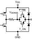
The LMT70 is a precision analog output temperature sensor. It includes an output switch that is controlled by the T_ON digital input. The output switch enables the multiplexing of several devices onto a single ADC input thus expanding on the ADC input multiplexer capability.
The temperature sensing element is comprised of simply stacked BJT base emitter junctions that are biased by a current source. The temperature sensing element is then buffered by a precision amplifier before being connected to the output switch. The output amplifier has a simple class AB push-pull output stage that enables the device to easily source and sink current.
The TAO push-pull output provides the ability to sink and source current. This is beneficial when, for example, driving dynamic loads like an input stage on an analog-to-digital converter (ADC). In these applications the source current is required to quickly charge the input capacitor of the ADC. See the Typical Application section for more discussion of this topic. The LMT70 is ideal for this and other applications which require strong source or sink current.
The LMT70 output voltage transfer function appears to be linear, but upon close inspection it can be seen that it is truly not linear and can be better described by a second or third order transfer function equation.
A first order transfer function can be used to calculate the temperature LMT70 is sensing but over a wide temperature range it is the least accurate method. An equation can be easily generated using the LUT (Look-Up Table) information found in Electrical Characteristics Temperature Lookup Table (LUT) .
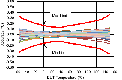
Over a narrow 10°C temperature range a linear equation will yield very accurate results. It is actually recommended that over a 10°C temperature range linear interpolation be used to calculate the temperature the device is sensing. When this method is used the accuracy minimum and maximum specifications would meet the values given in Figure 3.
For example the first order equation between 20°C and 30°C can be generated using the typical output voltage levels as given in Electrical Characteristics Temperature Lookup Table (LUT) and partially repeated here for reference from 20°C to 50°C:
Temperature (°C) | VTAO (mV) | Local Slope (mV/°C) | ||
---|---|---|---|---|
MIN | TYP | MAX | ||
20 | 994.367 | 995.050 | 995.734 | -5.171 |
30 | 942.547 | 943.227 | 943.907 | -5.194 |
40 | 890.423 | 891.178 | 891.934 | -5.217 |
50 | 838.097 | 838.882 | 839.668 | -5.241 |
First calculate the slope:
m =(T1 – T2) ÷ [(VTAO (T1) – VTAO (T2)]
m = (20°C - 30°C) ÷ (995.050 mV – 943.227 mV)
m = –0.193 °C/mV
Then calculate the y intercept b:
b = (T1) – (m × VTAO(T1))
b = 20°C – (–0.193 °C/mV × 995.050 mV)
b = 212.009°C
Thus the final equation used to calculate the measured temperature (TM) in the range between 20°C and 30°C is:
TM = m × VTAO + b
TM = –0.193 °C/mV × VTAO + 212.009°C
where VTAO is in mV and TM is in °C.
A second order transfer function can give good results over a wider limited temperature range. Over the full temperature range of -55°C to +150°C a single second order transfer function will have increased error at the temperature extremes. Using least squares sum method a best fit second order transfer function was generated using the values in Electrical Characteristics Temperature Lookup Table (LUT):
TM = a (VTAO)2+ b (VTAO) + c
where:
Best fit for -55°C to 150°C | Best fit for -10°C to 110°C | |
---|---|---|
a | -8.451576E-06 | -7.857923E-06 |
b | -1.769281E-01 | -1.777501E-01 |
c | 2.043937E+02 | 2.046398E+02 |
and VTAO is in mV and TM is in °C.
Over a wide temperature range the most accurate single equation is a third order transfer function. Using least squares sum method a best fit third order transfer function was generated using the values in Figure 3:
TM = a (VTAO)3 + b (VTAO)2 + c(VTAO) + d
where:
Best fit for -55°C to 150°C | Best fit for -10°C to 110°C | |
---|---|---|
a | -1.064200E-09 | -1.809628E-09 |
b | -5.759725E-06 | -3.325395E-06 |
c | -1.789883E-01 | -1.814103E-01 |
d | 2.048570E+02 | 2.055894E+02 |
and VTAO is in mV and TM is in °C.
In order to meet the matching specification of the LMT70A, two units must be picked from adjacent positions from one tape and reel. If PCB rework is required, involving the LMT70A, then the pair of the LMT70A matched units must be replaced. Matching features (which include, without limitation, electrical matching characteristics of adjacent Components as they are delivered in original packaging from TI) are warranted solely to the extent that the purchaser can demonstrate to TI’s satisfaction that the particular Component(s) at issue were adjacent in original packaging as delivered by TI. Customers should be advised that the small size of these components means they are not individually traceable at the unit level and it may be difficult to establish the original position of the Components once they have been removed from that original packaging as delivered by TI.
A load capacitor on TAO pin can help to filter noise.
For noisy environments, TI recommends at minimum 100 nF supply decoupling capacitor placed close across VDD and GND pins of LMT70.
TAO handles capacitive loading well. In an extremely noisy environment, or when driving a switched sampling input on an ADC, it may be necessary to add some filtering to minimize noise coupling. Without any precautions, the VTAO can drive a capacitive load less than or equal to 1 nF as shown in Figure 24. For capacitive loads greater than 1 nF, a series resistor is required on the output, as shown in Figure 25, to maintain stable conditions.
CLOAD | Minimum RS |
---|---|
1.1 to 90 nF | 3 kΩ |
90 to 900 nF | 1.5 kΩ |
0.9 μF | 750 Ω |
The T_ON digital input enables and disables the analog output voltage presented at the TAO pin by controlling the state of the internal switch that is in series with the internal temperature sensor circuitry output. When T_ON is driven to a logic "HIGH" the temperature sensor output voltage is present on the TAO pin. When T_ON is set to a logic "LOW" the TAO pin is set to a high impedance state.
Although the LMT70 package has a protective backside coating that reduces the amount of light exposure on the die, unless it is fully shielded, ambient light will still reach the active region of the device from the side of the package. Depending on the amount of light exposure in a given application, an increase in temperature error should be expected. In circuit board tests under ambient light conditions, a typical increase in error may not be observed and is dependent on the angle that the light approaches the package. The LMT70 is most sensitive to IR radiation. Best practice should include end-product packaging that provides shielding from possible light sources during operation.
The LMT70 is a simple precise analog output temperature sensor with a switch in series with its output. It has only two functional modes: output on or output off.
NOTE
Information in the following applications sections is not part of the TI component specification, and TI does not warrant its accuracy or completeness. TI’s customers are responsible for determining suitability of components for their purposes. Customers should validate and test their design implementation to confirm system functionality.
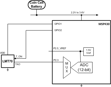
The LMT70 analog output temperature sensor is an ideal device to connect to an integrated 12-Bit ADC such as that found in the MSP430 microcontroller family.
Applications for the LMT70 included but are not limited to: IoT based temperature sensor nodes, medical fitness equipment (e.g. thermometers, fitness/smart bands or watches, activity monitors, human body temperature monitor), Class AA or lower RTD replacement, precision NTC or PTC thermistor replacement, instrumentation temperature compensation, metering temperature compensation (e. g. heat cost allocator, heat meter).
Most CMOS ADCs found in microcontrollers and ASICs have a sampled data comparator input structure. When the ADC charges the sampling cap, it requires instantaneous charge from the output of the analog source such as the LMT70 temperature sensor and many op amps. This requirement is easily accommodated by the addition of a capacitor (CFILTER) or the extension of the ADC acquisition time thus slowing the ADC sampling rate. The size of CFILTER depends on the size of the sampling capacitor and the sampling frequency. Since not all ADCs have identical input stages, the charge requirements will vary. The general ADC application shown in Figure 27 is an example only. The application in Figure 26 was actually tried and the extension of the MSP430 12-Bit ADC acquisition time was all that was necessary in order to accommodate the LMT70's output stage drive capability.
The circuit show in Figure 26 will support the design requirements as shown in Table 3.
PARAMETER | TARGET SPECIFICATION |
---|---|
Temperature Range | -40°C to +150°C LMT70, -40°C to +85°C for MSP430 |
Accuracy | ±0.2°C typical over full temperature range |
VDD | 2.2V to 3.6V with typical of 3.0V |
IDD | 12µA |
Of the three algorithms presented in this datasheet, linear interpolation, second order transfer function or third order transfer function, the one selected will be determined by the users microcontroller resources and the temperature range that will be sensed. Therefore, a comparison of the expected accuracy from the LMT70 is given here. The following curves show effect on the accuracy of the LMT70 when using each of the different algorithms/equations given in LMT70 Output Transfer Function. The first curve (Figure 28) shows the performance when using linear interpolation of the LUT values shown in Electrical Characteristics Temperature Lookup Table (LUT) of every 10°C and provides the best performance. Linear interpolation of the LUT values shown in Electrical Characteristics Temperature Lookup Table (LUT) is used to determine the LMT70 min/max accuracy limits as shown in the Electrical Characteristics and the red lines of Figure 28. The other lines in the middle of Figure 28 show independent device performance. The green limit lines, shown in the subsequent figures, apply for the specific equation used to convert the output voltage of the LMT70 to temperature. The equations are shown under each figure for reference purposes. The green lines show the min/max limits when set in a similar manner to the red limit lines of Figure 28. The limits shown in red for Figure 28 are repeated in all the figures of this section for comparison purposes.
Temp (°C) |
VTAO (mV) | Local Slope (mV/°C) |
||
---|---|---|---|---|
MIN | TYP | MAX | ||
20 | 994.367 | 995.050 | 995.734 | -5.171 |
30 | 942.547 | 943.227 | 943.907 | -5.194 |
40 | 890.423 | 891.178 | 891.934 | -5.217 |
50 | 838.097 | 838.882 | 839.668 | -5.241 |
TM = -1.809628E-09 (VTAO)3 – 3.325395E-06 (VTAO)2 – 1.814103E-01(VTAO) + 2.055894E+02 |
TM = -7.857923E-06 (VTAO)2 – 1.777501E-01 (VTAO) + 2.046398E+02 |
TM = -1.064200E-09 (VTAO)3 – 5.759725E-06 (VTAO)2 – 1.789883E-01(VTAO) + 2.048570E+02 | ||
TM = -8.451576E-06 (VTAO)2– 1.769281E-01 (VTAO) + 2.043937E+02 |
The ADC resolution and its specifications as well as reference voltage and its specifications will determine the overall system accuracy that you can obtain. For this example the 12-bit SAR ADC found in the MSP430 was used as well as it's integrated reference. At first glance the specifications may not seem to be precise enough to actually be used with the LMT70 but the MSP430 ADC and integrated reference errors are actually measured during production testing of the MSP430. Values are then provided to user for software calibration. These calibration values are located in the MSP430A device descriptor tag-length-value (TLV) structure and found in the device-specific datasheet. The MSP430 Users Guide includes information on how to use these calibration values to calibrate the ADC reading. The specific values used to calibrate the ADC readings are: CAL_ADC_15VREF_FACTOR, CAL_ADC_GAIN_FACTOR and CAL_ADC_OFFSET.
The following table is given for reference only and not meant to be used for calculation purposes.
Temp (°C) |
VTAO
(mV) |
Temp (°C) |
VTAO
(mV) |
Temp (°C) |
VTAO
(mV) |
Temp (°C) |
VTAO
(mV) |
Temp (°C) |
VTAO
(mV) |
Temp (°C) |
VTAO
(mV) |
Temp (°C) |
VTAO
(mV) |
Temp (°C) |
VTAO
(mV) |
|||||||
TYP | TYP | TYP | TYP | TYP | TYP | TYP | TYP | |||||||||||||||
-30 | 1250.398 | 0 | 1097.987 | 30 | 943.227 | 60 | 786.360 | 90 | 627.490 | 120 | 466.760 | 150 | 302.785 | |||||||||
-29 | 1244.953 | 1 | 1092.532 | 31 | 937.729 | 61 | 780.807 | 91 | 621.896 | 121 | 460.936 | |||||||||||
-28 | 1239.970 | 2 | 1087.453 | 32 | 932.576 | 62 | 775.580 | 92 | 616.603 | 122 | 455.612 | |||||||||||
-27 | 1234.981 | 3 | 1082.370 | 33 | 927.418 | 63 | 770.348 | 93 | 611.306 | 123 | 450.280 | |||||||||||
-26 | 1229.986 | 4 | 1077.282 | 34 | 922.255 | 64 | 765.113 | 94 | 606.006 | 124 | 444.941 | |||||||||||
-55 | 1375.219 | -25 | 1224.984 | 5 | 1072.189 | 35 | 917.087 | 65 | 759.873 | 95 | 600.701 | 125 | 439.593 | |||||||||
-54 | 1370.215 | -24 | 1219.977 | 6 | 1067.090 | 36 | 911.915 | 66 | 754.628 | 96 | 595.392 | 126 | 434.238 | |||||||||
-53 | 1365.283 | -23 | 1214.963 | 7 | 1061.987 | 37 | 906.738 | 67 | 749.380 | 97 | 590.079 | 127 | 428.875 | |||||||||
-52 | 1360.342 | -22 | 1209.943 | 8 | 1056.879 | 38 | 901.556 | 68 | 744.127 | 98 | 584.762 | 128 | 423.504 | |||||||||
-51 | 1355.395 | -21 | 1204.916 | 9 | 1051.765 | 39 | 896.370 | 69 | 738.870 | 99 | 579.442 | 129 | 418.125 | |||||||||
-50 | 1350.441 | -20 | 1199.884 | 10 | 1046.647 | 40 | 891.178 | 70 | 733.608 | 100 | 574.117 | 130 | 412.739 | |||||||||
-49 | 1345.159 | -19 | 1194.425 | 11 | 1041.166 | 41 | 885.645 | 71 | 728.055 | 101 | 568.504 | 131 | 406.483 | |||||||||
-48 | 1340.229 | -18 | 1189.410 | 12 | 1036.062 | 42 | 880.468 | 72 | 722.804 | 102 | 563.192 | 132 | 401.169 | |||||||||
-47 | 1335.293 | -17 | 1184.388 | 13 | 1030.952 | 43 | 875.287 | 73 | 717.550 | 103 | 557.877 | 133 | 395.841 | |||||||||
-46 | 1330.352 | -16 | 1179.361 | 14 | 1025.838 | 44 | 870.100 | 74 | 712.292 | 104 | 552.557 | 134 | 390.499 | |||||||||
-45 | 1325.405 | -15 | 1174.327 | 15 | 1020.720 | 45 | 864.909 | 75 | 707.029 | 105 | 547.233 | 135 | 385.144 | |||||||||
-44 | 1320.453 | -14 | 1169.288 | 16 | 1015.596 | 46 | 859.713 | 76 | 701.762 | 106 | 541.905 | 136 | 379.775 | |||||||||
-43 | 1315.496 | -13 | 1164.242 | 17 | 1010.467 | 47 | 854.513 | 77 | 696.491 | 107 | 536.573 | 137 | 374.393 | |||||||||
-42 | 1310.534 | -12 | 1159.191 | 18 | 1005.333 | 48 | 849.307 | 78 | 691.217 | 108 | 531.236 | 138 | 368.997 | |||||||||
-41 | 1305.566 | -11 | 1154.134 | 19 | 1000.194 | 49 | 844.097 | 79 | 685.937 | 109 | 525.895 | 139 | 363.587 | |||||||||
-40 | 1300.593 | -10 | 1149.070 | 20 | 995.050 | 50 | 838.882 | 80 | 680.654 | 110 | 520.551 | 140 | 358.164 | |||||||||
-39 | 1295.147 | -9 | 1143.654 | 21 | 989.583 | 51 | 833.343 | 81 | 675.073 | 111 | 514.886 | 141 | 351.937 | |||||||||
-38 | 1290.202 | -8 | 1138.599 | 22 | 984.450 | 52 | 828.141 | 82 | 669.803 | 112 | 509.557 | 142 | 346.508 | |||||||||
-37 | 1285.250 | -7 | 1133.540 | 23 | 979.313 | 53 | 822.934 | 83 | 664.528 | 113 | 504.223 | 143 | 341.071 | |||||||||
-36 | 1280.291 | -6 | 1128.476 | 24 | 974.171 | 54 | 817.723 | 84 | 659.250 | 114 | 498.885 | 144 | 335.625 | |||||||||
-35 | 1275.326 | -5 | 1123.407 | 25 | 969.025 | 55 | 812.507 | 85 | 653.967 | 115 | 493.542 | 145 | 330.172 | |||||||||
-34 | 1270.353 | -4 | 1118.333 | 26 | 963.875 | 56 | 807.287 | 86 | 648.680 | 116 | 488.195 | 146 | 324.711 | |||||||||
-33 | 1265.375 | -3 | 1113.254 | 27 | 958.720 | 57 | 802.062 | 87 | 643.389 | 117 | 482.843 | 147 | 319.241 | |||||||||
-32 | 1260.389 | -2 | 1108.170 | 28 | 953.560 | 58 | 796.832 | 88 | 638.094 | 118 | 477.486 | 148 | 313.764 | |||||||||
-31 | 1255.397 | -1 | 1103.081 | 29 | 948.396 | 59 | 791.598 | 89 | 632.794 | 119 | 472.125 | 149 | 308.279 |
The LMT70 performance using the MSP430 with integrated 12-bit ADC is shown in Figure 33. This curve includes the error of the MSP430 integrated 12-bit ADC and reference as shown in the schematic Figure 26. The MSP430 was kept at room temperature and the LMT70 was submerged in a precision temperature calibration oil bath. A calibrated temperature probe was used to monitor the temperature of the oil. As can be seen in Figure 33 the combined performance on the MSP430 and the LMT70 is better than 0.12°C for the entire -40°C to +150°C temperature range. The only calibration performed was with software using the MSP430A device descriptor tag-length-value (TLV) calibration values for ADC and VREF error.