TIDT247 February 2022
Description
This design features an automotive backup battery system using a 1S Li battery for emergency operation.
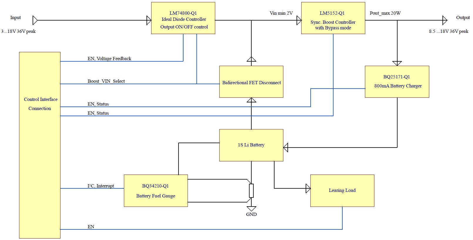
The primary power input is rated for 6- to 18-V nominal (2.7- to 36-V peak) to comply with 12-V automotive requirements. The secondary power input is equipped with a fuel gauge to monitor a single cell Li battery and supports input voltages from 2 V to 4.35 V. The onboard learning load allows the easy implementation of an end-of-life detection for the backup battery.
Both power inputs are connected via ORing MOSFET switches to an 8.5-V boost converter, which can deliver up to 21.5-W continuous output power (30-W peak) with 2.5-V input voltage. At lower output currents, the input voltage of the boost converter can be as low as 2 V.
Due to the ORing MOSFET switches, this boost converter covers the emergency operation as well as cold crank situations, where the 12-V rail can drop down to 2.7 V at the primary input.
An ideal diode together with the bypass function of the boost stage minimizes losses during normal operation and allows low cold-crank voltages. Additionally, the ideal diode allows disconnecting the load on demand.
For ease of evaluation, an automated switchover between primary and secondary power input is implemented on this design.
The total power solution is completed by a linear battery charger for the Li battery, which can operate at input voltages as high as 18 V and withstand 40-V spikes during load dumps. The charger supports various cell chemistries.
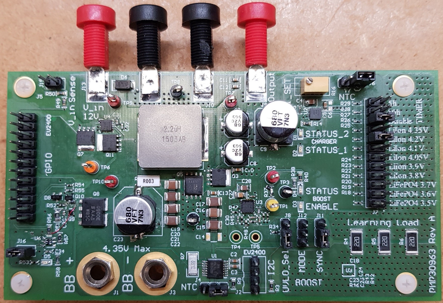
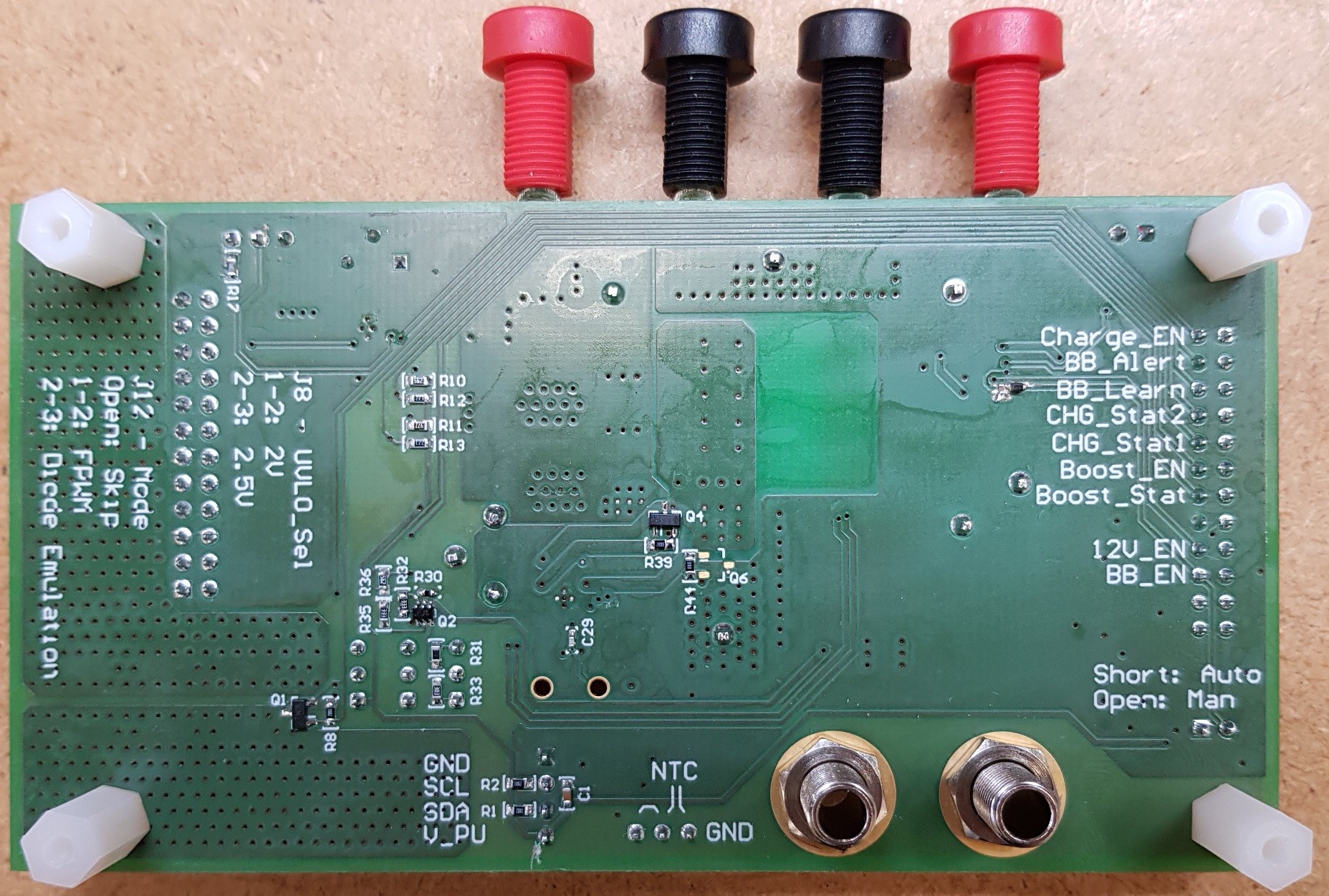
The following images shown the top and bottom photos of the 4-layer PCB, FR4, with 35-µm copper.
 Board Top
 Board Bottom
 Block Diagram