TIDT247 February 2022
4.2 Control Loop
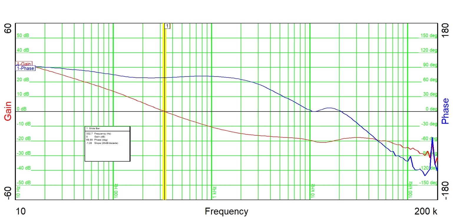
The control loop is measured at 2.5 VIN, 3-A load current, the temperature was 68.8°C with a phase margin at 322.7 Hz.
 Figure 4-2 Control Loop - Bode
Plot
Figure 4-2 Control Loop - Bode
PlotTIDT247 February 2022
The control loop is measured at 2.5 VIN, 3-A load current, the temperature was 68.8°C with a phase margin at 322.7 Hz.
 Figure 4-2 Control Loop - Bode
Plot