-
INA165x-Q1 SoundPlus™ 高共模抑制线路接收器 ZHCSGP4C August 2017 – May 2019 INA1650-Q1 , INA1651-Q1
PRODUCTION DATA.
DATA SHEET
INA165x-Q1 SoundPlus™ 高共模抑制线路接收器
本资源的原文使用英文撰写。 为方便起见,TI 提供了译文;由于翻译过程中可能使用了自动化工具,TI 不保证译文的准确性。 为确认准确性,请务必访问 ti.com 参考最新的英文版本(控制文档)。
1 特性
- 符合面向汽车应用的 AEC-Q100 标准
- 温度等级 1:–40°C 至 +125°C,TA
- 高共模抑制:91dB(典型值)
- 高输入阻抗:1MΩ 差分
- 超低噪声:-104.7dBu,未加权
- 超低总谐波失真 + 噪声:
-119dB THD+N(20dBu,22kHz 带宽) - 短路保护
- 集成电磁干扰 (EMI) 滤波器
- 宽电源电压范围:±2.25V 至 ±12V
- 采用小型 14 引脚 TSSOP 封装
2 应用
- 车厢麦克风前置放大器
- 信息娱乐系统
- 音频输入电路
- 线路驱动器
- 外部音频功率放大器
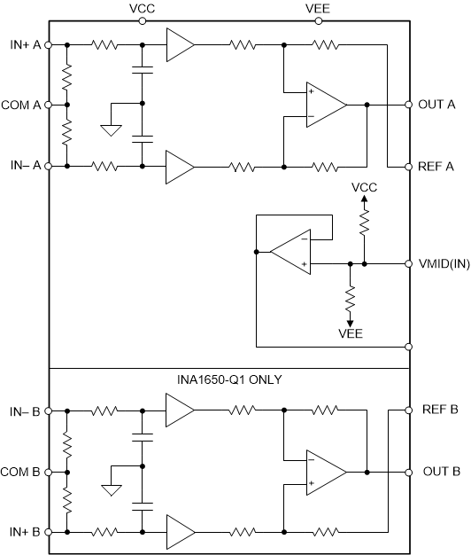
简化内部原理图

3 说明
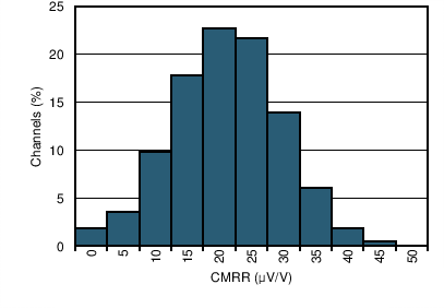
INA1650-Q1 双通道和 INA1651-Q1 单通道 (INA165x-Q1) SoundPlus™音频线路接收器可实现 91dB 的极高共模抑制比 (CMRR),与此同时,对于 20dBu 信号电平,可在 1kHz 时保持 -119dB 的超低 THD+N。不同于其他线路接收器产品,INA165x-Q1 CMRR 在额定温度范围内能保持特性不变,经生产测试,可在各种应用中提供稳定的 性能。
INA165x-Q1 器件支持 ±2.25V 至 ±12V 的极宽电源电压范围。除线路接收器通道以外,INA165x-Q1 还包含一个缓冲 1/2 Vs 基准输出,因此可配置为用于双电源或单电源 应用。1/2 Vs 输出可用作信号链中的另一个模拟电路的偏置电压。
INA1650-Q1 具有 独特的内部布局,即使在过驱或过载条件下也可在通道间实现最低串扰和零交互。
器件信息(1)
| 器件型号 | 封装 | 封装尺寸(标称值) |
|---|---|---|
| INA1650-Q1 | TSSOP (14) | 5.00mm × 4.40mm |
| INA1651-Q1 |
- 如需了解所有可用封装,请参阅数据表末尾的封装选项附录。
CMRR 直方图(5746 通道)

4 修订历史记录
Changes from B Revision (April 2019) to C Revision
- Changed ESD Ratings table to show individual device ratings Go
Changes from A Revision (October 2017) to B Revision
- Added 向数据表中添加了 INA1651-Q1 器件和相关内容Go
Changes from * Revision (August 2017) to A Revision
- INA1650-Q1 的建议电源电压范围从 36V 降到了 24V。文本、图表和电路图中提及的所有 36V 工作电压都已删除或修改,以反映 24V 的最大电源电压。Go
5 Pin Configuration and Functions
INA1650-Q1 PW Package
14-Pin TSSOP
Top View
Pin Functions: INA1650-Q1
| PIN | I/O | DESCRIPTION | |
|---|---|---|---|
| NAME | NO. | ||
| COM A | 3 | I | Input common, channel A |
| COM B | 6 | I | Input common, channel B |
| IN+ A | 2 | I | Noninverting input, channel A |
| IN– A | 4 | I | Inverting input, channel A |
| IN+ B | 7 | I | Noninverting input, channel B |
| IN– B | 5 | I | Inverting input, channel B |
| OUT A | 13 | O | Output, channel A |
| OUT B | 8 | O | Output, channel B |
| REF A | 12 | I | Reference input, channel A. This pin must be driven from a low impedance. |
| REF B | 9 | I | Reference input, channel B. This pin must be driven from a low impedance. |
| VCC | 1 | — | Positive (highest) power supply |
| VEE | 14 | — | Negative (lowest) power supply |
| VMID(IN) | 11 | I | Input node of internal supply divider. Connect a capacitor to this pin to reduce noise from the supply divider circuit. |
| VMID(OUT) | 10 | O | Buffered output of internal supply divider. |
INA1651-Q1 PW Package
14-Pin TSSOP
Top View
Pin Functions: INA1651-Q1
| PIN | I/O | DESCRIPTION | |
|---|---|---|---|
| NAME | NO. | ||
| COM A | 3 | I | Input common, channel A |
| IN+ A | 2 | I | Noninverting input, channel A |
| IN– A | 4 | I | Inverting input, channel A |
| NC | 5 | — | No internal connection |
| NC | 6 | — | No internal connection |
| NC | 7 | — | No internal connection |
| NC | 8 | — | No internal connection |
| NC | 9 | — | No internal connection |
| OUT A | 13 | O | Output, channel A |
| REF A | 12 | I | Reference input, channel A. This pin must be driven from a low impedance. |
| VCC | 1 | — | Positive (highest) power supply |
| VEE | 14 | — | Negative (lowest) power supply |
| VMID(IN) | 11 | I | Input node of internal supply divider. Connect a capacitor to this pin to reduce noise from the supply divider circuit. |
| VMID(OUT) | 10 | O | Buffered output of internal supply divider. |