• Menu
  • Product
  • Email
  • PDF
  • Order now
  • TPS61170-Q1 采用 2mm x 2mm SON 封装的 1.2A 升压转换器

    • ZHCS253A September   2011  – July 2015 TPS61170-Q1

      PRODUCTION DATA.  

  • CONTENTS
  • SEARCH
  • TPS61170-Q1 采用 2mm x 2mm SON 封装的 1.2A 升压转换器
  1. 1 特性
  2. 2 应用范围
  3. 3 说明
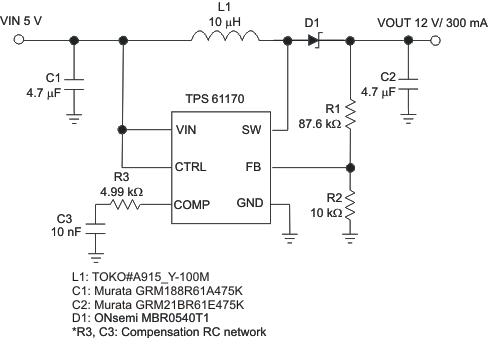
  4. 4 典型应用
  5. 5 修订历史记录
  6. 6 Pin Configuration and Functions
  7. 7 Specifications
    1. 7.1 Absolute Maximum Ratings
    2. 7.2 ESD Ratings
    3. 7.3 Recommended Operating Conditions
    4. 7.4 Thermal Information
    5. 7.5 Electrical Characteristics
    6. 7.6 Switching Characteristics
    7. 7.7 Typical Characteristics
  8. 8 Detailed Description
    1. 8.1 Overview
    2. 8.2 Functional Block Diagram
    3. 8.3 Feature Description
      1. 8.3.1 Soft Start-up
      2. 8.3.2 Overcurrent Protection
      3. 8.3.3 Undervoltage Lockout
      4. 8.3.4 Thermal Shutdown
      5. 8.3.5 Enable and Shutdown
    4. 8.4 Device Functional Modes
      1. 8.4.1 PWM Program Mode
      2. 8.4.2 1-Wire Program Mode
      3. 8.4.3 EasyScale
    5. 8.5 Programming
      1. 8.5.1 Feedback Reference Program Mode Selection
  9. 9 Application and Implementation
    1. 9.1 Application Information
    2. 9.2 Typical Applications
      1. 9.2.1 12-V to 24-V DC-DC Power Conversion
        1. 9.2.1.1 Design Requirements
        2. 9.2.1.2 Detailed Design Procedure
          1. 9.2.1.2.1 Program Output Voltage
          2. 9.2.1.2.2 Maximum Output Current
          3. 9.2.1.2.3 Switch Duty Cycle
          4. 9.2.1.2.4 Inductor Selection
          5. 9.2.1.2.5 Schottky Diode Selection
          6. 9.2.1.2.6 Compensation Capacitor Selection
          7. 9.2.1.2.7 Input and Output Capacitor Selection
        3. 9.2.1.3 Application Curve
      2. 9.2.2 5-V to 12-V DC-DC Power Conversion With Programmable Feedback Reference Voltage
      3. 9.2.3 12-V SEPIC (Buck-Boost) Converter
  10. 10Power Supply Recommendations
  11. 11Layout
    1. 11.1 Layout Guidelines
    2. 11.2 Layout Example
    3. 11.3 Thermal Considerations
  12. 12器件和文档支持
    1. 12.1 器件支持
      1. 12.1.1 Third-Party Products Disclaimer
    2. 12.2 文档支持
      1. 12.2.1 相关文档 
    3. 12.3 社区资源
    4. 12.4 商标
    5. 12.5 静电放电警告
    6. 12.6 Glossary
  13. 13机械、封装和可订购信息
  14. 重要声明
search No matches found.
  • Full reading width
    • Full reading width
    • Comfortable reading width
    • Expanded reading width
  • Card for each section
  • Card with all content


DATA SHEET

TPS61170-Q1 采用 2mm x 2mm SON 封装的 1.2A 升压转换器

本资源的原文使用英文撰写。 为方便起见,TI 提供了译文;由于翻译过程中可能使用了自动化工具,TI 不保证译文的准确性。 为确认准确性,请务必访问 ti.com 参考最新的英文版本(控制文档)。

1 特性

  • 适用于汽车电子 应用
  • 3V 至 18V 输入电压范围
  • 输入电压最高可达 38V
  • 1.2A 集成开关
  • 1.2MHz 固定开关频率
  • 由 5V 输入电压供电时,300mA 对应的输出电压为 12V,150mA 对应的输出电压为 24V(典型值)
  • 效率高达 93%
  • 实时输出电压重编程
  • 轻载条件下输出调节可跳过开关周期
  • 内置软启动
  • 6 引脚,2mm × 2mm 小外形尺寸无引线 (SON) 封装

2 应用范围

  • 混合动力汽车 (HEV) 和电动汽车 (EV) 充电器系统
  • 高级驾驶员辅助系统 (ADAS)

3 说明

TPS61170-Q1 是一款集成 1.2A/40V 功率金属氧化物半导体场效应晶体管 (MOSFET) 的单片高压开关稳压器。该器件可配置为多种标准开关稳压器拓扑,包括升压和 SEPIC。该器件通过其宽输入电压范围 支持 需要由多节电池或经稳压的 5V/12V 电源轨提供输电压的应用。

TPS61170-Q1 的工作开关频率为 1.2MHz,允许使用薄型电感和低值陶瓷输入和输出电容。外部回路补偿组件支持用户灵活优化回路补偿和瞬态响应。此器件内置保护 特性,例如逐脉冲过流限制、软启动和热关断。

FB 引脚可调节为基准电压
1.229V。该基准电压可使用通过 CTRL 引脚连接的单线制数字接口(EasyScale™协议)进行降低。另外,也可将一路脉宽调制 (PWM) 信号施加于 CTRL 引脚。该信号的占空比可按比例降低反馈基准电压。

TPS61170-Q1 采用 6 引脚 2mm ×
2mm SON 封装,适用于紧凑型电源解决方案。

器件信息(1)

器件型号 封装 封装尺寸(标称值)
TPS61170-Q1 SON (6) 2.00mm x 2.00mm
  1. 要了解所有可用封装,请见数据表末尾的可订购产品附录。

4 典型应用

TPS61170-Q1 typ_app_lvs789.gif

5 修订历史记录

Changes from * Revision (September 2011) to A Revision

  • Added ESD 额定值表,特性 描述 部分,器件功能模式,应用和实施部分,电源相关建议部分,布局部分,器件和文档支持部分以及机械、封装和可订购信息部分Go

6 Pin Configuration and Functions

DRV Package
6-Pin SON With Exposed Thermal Pad
Top View
TPS61170-Q1 po_lvs789.gif

Pin Functions

PIN I/O DESCRIPTION
NAME NO.
COMP 2 O Output of the transconductance error amplifier. Connect an external RC network to this pin to compensate the regulator.
CTRL 5 I Control pin of the boost regulator. CTRL is a multi-functional pin which can be used to enable the device and control the feedback voltage with a PWM signal or for digital communications.
FB 1 I Feedback pin for current. Connect to the center tap of a resistor divider to program the output voltage.
GND 3 O Ground
SW 4 I This is the switching node of the IC. Connect SW to the switched side of the inductor.
VIN 6 I The input supply pin for the IC. Connect VIN to a supply voltage between 3 V and 18 V.
Thermal Pad — The thermal pad should be soldered to the analog ground plane to avoid thermal issue. If possible, use thermal vias to connect to ground plane for ideal power dissipation.

7 Specifications

7.1 Absolute Maximum Ratings

over operating free-air temperature range (unless otherwise noted) (1)
MIN MAX UNIT
VI Supply voltages on VIN (2) –0.3 20 V
Voltages on CTRL(2) –0.3 20
Voltage on FB and COMP(2) –0.3 3
Voltage on SW(2) –0.3 40
PD Continuous power dissipation See Thermal Information
TJ Operating junction temperature –40 150 °C
Tstg Storage temperature –65 150 °C
(1) Stresses beyond those listed under Absolute Maximum Ratings may cause permanent damage to the device. These are stress ratings only, and functional operation of the device at these or any other conditions beyond those indicated under Recommended Operating Conditions is not implied. Exposure to absolute-maximum-rated conditions for extended periods may affect device reliability.
(2) All voltage values are with respect to network ground terminal.

7.2 ESD Ratings

VALUE UNIT
V(ESD) Electrostatic discharge Human body model (HBM), per ANSI/ESDA/JEDEC JS-001, all pins(1) ±2000 V
Charged device model (CDM), per JEDEC specification JESD22-C101, all pins Corner pins (FB, GND, VIN, and SW) ±750
Other pins ±500
(1) AEC Q100-002 indicates that HBM stressing shall be in accordance with the ANSI/ESDA/JEDEC JS-001 specification.

7.3 Recommended Operating Conditions

MIN NOM MAX UNIT
VI Input voltage range, VIN 3 18 V
VO Output voltage range VIN 38 V
L Inductor(1) 10 22 μH
CI Input capacitor 1 μF
CO Output capacitor(1) 1 10 μF
TA Operating ambient temperature –40 125 °C
TJ Operating junction temperature –40 125 °C
(1) These values are recommended values that have been successfully tested in several applications. Other values may be acceptable in other applications but should be fully tested by the user.

7.4 Thermal Information

THERMAL METRIC(1) TPS61170-Q1 UNIT
DRV (SON)
6 PINS
RθJA Junction-to-ambient thermal resistance 96.1 °C/W
RθJC(top) Junction-to-case (top) thermal resistance 89 °C/W
RθJB Junction-to-board thermal resistance 65.9 °C/W
ψJT Junction-to-top characterization parameter 3.2 °C/W
ψJB Junction-to-board characterization parameter 66.3 °C/W
RθJC(bot) Junction-to-case (bottom) thermal resistance 40.8 °C/W
(1) For more information about traditional and new thermal metrics, see the Semiconductor and IC Package Thermal Metrics application report, SPRA953.

7.5 Electrical Characteristics

VIN = 3.6 V, CTRL = VIN, TA = –40°C to 125°C, typical values are at TA = 25°C (unless otherwise noted)
PARAMETER TEST CONDITIONS MIN TYP MAX UNIT
SUPPLY CURRENT
VI Input voltage range, VIN 3.0 18 V
IQ Operating quiescent current into VIN Device PWM switching no load 2.3 mA
ISD Shutdown current CRTL = GND, VIN = 4.2 V 1 μA
UVLO Undervoltage lockout threshold VIN falling 2.2 2.5 V
Vhys Undervoltage lockout Hysteresis 70 mV
ENABLE AND REFERENCE CONTROL
V(CTRLh) CTRL logic high voltage VIN = 3 V to 18 V 1.2 V
V(CTRL) CTRL logic low voltage VIN = 3 V to 18 V 0.4 V
R(CTRL) CTRL pulldown resistor 400 800 1600 kΩ
VOLTAGE AND CURRENT CONTROL
VREF Voltage feedback regulation voltage 1.204 1.229 1.254 V
V(REF_PWM) Voltage feedback regulation voltage under reprogram VFB = 492 mV 477 492 507 mV
IFB Voltage feedback input bias current VFB = 1.229 V 200 nA
Dmax Maximum duty cycle VFB = 100 mV 90% 93%
Isink Comp pin sink current 100 μA
Isource Comp pin source current 100 μA
Gea Error amplifier transconductance 240 320 400 μmho
Rea Error amplifier output resistance 5 pF connected to COMP 6 MΩ
POWER SWITCH
RDS(on) N-channel MOSFET ON-resistance VIN = 3.6 V 0.3 0.6 Ω
VIN = 3.0 V 0.7
ILN_NFET N-channel leakage current VSW = 35 V, TA = 25°C 1 μA
OC AND SS
ILIM N-channel MOSFET current limit D = Dmax 0.96 1.2 1.44 A
ILIM_Start Start-up current limit D = Dmax 0.7 A
EasyScale TIMING
VACKNL Acknowledge output voltage low Open-drain, Rpullup =15 kΩ to Vin 0.4 V
THERMAL SHUTDOWN
Tshutdown Thermal shutdown threshold 160 °C
Thysteresis Thermal shutdown threshold hysteresis 15 °C
(1) Acknowledge condition active 0, this condition will only be applied if the RFA bit is set. Open-drain output, line must be pulled high by the host with resistor load.

7.6 Switching Characteristics

VIN = 3.6 V, CTRL = VIN, TA = –40°C to 125°C, typical values are at TA = 25°C (unless otherwise noted)
PARAMETER TEST CONDITIONS MIN TYP MAX UNIT
ENABLE AND REFERENCE CONTROL
toff EasyScale detection time(1) CTRL high to low 2.5 ms
tes_det EasyScale detection time(1) CTRL pin low 260 μs
tes_delay EasyScale detection delay 100 μs
tes_win EasyScale detection window time 1 ms
VOLTAGE AND CURRENT CONTROL
fS Oscillator frequency 1 1.2 1.5 MHz
tmin_on Minimum on pulse width 40 ns
fea Error amplifier crossover frequency 5 pF connected to COMP 500 kHz
OC AND SS
tHalf_LIM Time step for half current limit 5 ms
tREF Vref filter time constant 180 μs
tstep VREF ramp-up time 213 μs
EasyScale TIMING
tstart Start time of program stream 2 μs
tEOS End time of program stream 2 360 μs
tH_LB High time low bit Logic 0 2 180 μs
tL_LB Low time low bit Logic 0 2 × tH_LB 360 μs
tH_HB High time high bit Logic 1 2 × tL_HB 360 μs
tL_HB Low time high bit Logic 1 2 180 μs
tvalACKN Acknowledge valid time See (1) 2 μs
tACKN Duration of acknowledge condition See (1) 512 μs
(1) EasyScale communication is allowed immediately after the CTRL pin has been low for more than tes_det. To select EasyScale mode, the CTRL pin must be low for more than tes_det the end of tes_win.

7.7 Typical Characteristics

L = TOKO A915_Y-100M, D1 = ONsemi MBR0540T1, unless otherwise noted

Table 1. Table of Graphs

典型应用 FIGURE
Efficiency VIN = 5V; VOUT = 12 V, 18 V, 24 V, 30 V Figure 17
Efficiency VIN = 5 V, 8.5 V, 12 V; VOUT = 24 V Figure 1
Output voltage accuracy ILOAD= 100 mA Figure 2
Switch current limit TA = 25°C Figure 3
Switch current limit Figure 4
Error amplifier transconductance Figure 5
EasyScale step Figure 6
PWM switching operation VIN = 5 V; VOUT = 12 V; ILOAD= 250 mA Figure 7
Load transient response VIN = 5 V; VOUT = 12 V; ILOAD= 50 mA to 150 mA Figure 8
Start-up VIN = 5 V; VOUT = 12 V; ILOAD= 250 mA Figure 9
Skip-cycle switching VIN = 9 V ; VOUT = 12 V, ILOAD= 100 μA Figure 10
TPS61170-Q1 eff2_io_lvs789.gif
Figure 1. Efficiency vs Output Current
TPS61170-Q1 swc_dc_lvs789.gif
Figure 3. Switch Current Limit vs Duty Cycle
TPS61170-Q1 error_ta_lvs789.gif
Figure 5. Error Amplifier Transconductance vs Temperature
TPS61170-Q1 pwm_sw_lvs789.gif
Figure 7. PWM Switching Operation
TPS61170-Q1 startup_lvs789.gif
Figure 9. Start-Up
TPS61170-Q1 vo_vi_lvs789.gif
Figure 2. Output Voltage vs Input Voltage
TPS61170-Q1 swc_ta_lvs789.gif
Figure 4. Switch Current Limit vs Temperature
TPS61170-Q1 fbv_scale_lvs789.gif
Figure 6. FB Voltage vs EasyScale Step
TPS61170-Q1 ld_trans_lvs789.gif
Figure 8. Load Transient Response
TPS61170-Q1 skip_cyc_lvs789.gif
Figure 10. Skip-Cycle Switching

8 Detailed Description

8.1 Overview

The TPS61170-Q1 integrates a 40-V low-side FET for providing output voltages up to 38 V. The device regulates the output with current mode PWM (pulse width modulation) control. The switching frequency of the PWM is fixed at 1.2 MHz (typical). The PWM control circuitry turns on the switch at the beginning of each switching cycle. The input voltage is applied across the inductor and stores the energy as the inductor current ramps up. During this portion of the switching cycle, the load current is provided by the output capacitor. When the inductor current rises to the threshold set by the error amplifier output, the power switch turns off and the external Schottky diode is forward biased. The inductor transfers stored energy to replenish the output capacitor and supply the load current. This operation repeats each switching cycle. As shown in the block diagram, the duty cycle of the converter is determined by the PWM control comparator which compares the error amplifier output and the current signal.

A ramp signal from the oscillator is added to the current ramp. This slope compensation ramp is necessary to avoid subharmonic oscillations that are intrinsic to current mode control at duty cycles higher than 50%. The feedback loop regulates the FB pin to a reference voltage through an error amplifier. The output of the error amplifier must be connected to the COMP pin. An external RC compensation network must be connected to the COMP pin to optimize the feedback loop for stability and transient response.

8.2 Functional Block Diagram

TPS61170-Q1 fbd_lvs789.gif

8.3 Feature Description

8.3.1 Soft Start-up

Soft-start circuitry is integrated into the IC to avoid a high inrush current during start-up. After the device is enabled by a logic high signal on the CTRL pin, the FB pin reference voltage ramps up in 32 steps, with each step taking 213 μs. This ensures that the output voltage rises slowly to reduce inrush current. Additionally, for the first 5 ms after the COMP voltage ramps, the current limit of the PWM switch is set to half of the normal current limit specification or below 700 mA (typical). For a typical example, see the start-up waveform (Figure 9).

8.3.2 Overcurrent Protection

TPS61170-Q1 has a cycle-by-cycle overcurrent limit feature that turns off the power switch once the inductor current reaches the overcurrent limit. The PWM circuitry resets itself at the beginning of the next switch cycle. During an overcurrent event, this results in a decrease of output voltage that is directly proportional to load current. The current limit threshold as well as input voltage, output voltage, switching frequency and inductor value determine the maximum available output current. Larger inductance values typically increase the current output capability because of the reduced current ripple. See the Application and Implementation section for the output current calculation.

8.3.3 Undervoltage Lockout

An undervoltage lockout (UVLO) prevents misoperation of the device at input voltages below 2.2 V (typical). When the input voltage is below the undervoltage threshold, the device remains off and the internal switch FET is turned off. The undervoltage lockout threshold is set below minimum operating voltage of 3 V to avoid any transient VIN dip triggering the UVLO and causing the device to reset. For the input voltages between UVLO threshold and 3 V, the device tries operation, but the specifications are not ensured.

8.3.4 Thermal Shutdown

An internal thermal shutdown turns off the device when the typical junction temperature of 160°C is exceeded. The IC restarts when the junction temperature drops by 15°C.

8.3.5 Enable and Shutdown

The TPS61170-Q1 device enters shutdown when the CTRL voltage is less than 0.4 V for more than 2.5 ms. In shutdown, the input supply current for the device is less than 1 μA (maximum). The CTRL pin has an internal 800-kΩ (typical) pulldown resistor to disable the device when the pin is left unconnected.

8.4 Device Functional Modes

8.4.1 PWM Program Mode

When the CTRL pin is constantly high, the FB voltage is regulated to 1.229 V typically. However, the CTRL pin allows a PWM signal to lower this regulation voltage. The relationship between the duty cycle and FB voltage is given in Equation 1:

Equation 1. TPS61170-Q1 q1_vfb_lvs789.gif

where

  • Duty = duty cycle of the PWM signal
  • 1.229 V = internal reference voltage

As shown in Figure 11, the IC chops up the internal 1.229-V reference voltage at the duty cycle of the PWM signal. The pulse signal is then filtered by an internal low-pass filter. The output of the filter is connected to the error amplifier as the reference voltage for the FB pin regulation. The regulation voltage is independent of the PWM logic voltage level which often has large variations.

For optimum performance, use the PWM mode in the range of 5 kHz to 100 kHz. The requirement of minimum frequency comes from the EasyScale detection delay and detection time specification for the mode selection. The device can mistakenly enter 1-wire mode if the PWM signal frequency is less than 5 kHz. Because there is an internal fixed ON-time error of 40 nS, the FB voltage absolute value will be different than expected when the PWM frequency is above 100 kHz. For example, the additional duty cycle of 3.2% due to the ON-time error increases the FB voltage when using an 800-kHz PWM signal. A compromise between PWM frequency and FB voltage accuracy extends the frequency range. Adding an external RC filter to the pin serves no purpose.

TPS61170-Q1 fb_v_bd_lvs789.gif Figure 11. Block Diagram of Programmable FB Voltage Using PWM Signal

8.4.2 1-Wire Program Mode

The CTRL pin features a simple digital interface to control the feedback reference voltage. The 1-wire mode can save the processor power and battery life as it does not require a PWM signal all the time, and the processor can enter idle mode if available.

The TPS61170-Q1 adopts the EasyScale protocol, which can program the FB voltage to any of the 32 steps with one command. See Table 2 for the FB pin voltage steps. The programmed reference voltage is stored in an internal register. The default value is full scale when the device is first enabled (VFB = 1.229 V). A power reset clears the register value and reset it to default.

8.4.3 EasyScale

EasyScale is a simple but very flexible 1-pin interface to configure the FB voltage. The interface is based on a master-slave structure, where the master is typically a microcontroller or application processor. Figure 12 and Table 2 give an overview of the protocol. The protocol consists of a device-specific address byte and a data byte. The device-specific address byte is fixed to 72 hex. The data byte consists of 5 bits for information, 2 address bits, and the RFA bit. The RFA bit set to high indicates the Request for Acknowledge condition. The Acknowledge condition is only applied if the protocol was received correctly. The advantage of EasyScale compared with other on pin interfaces is that its bit detection is in a large extent independent from the bit transmission rate. EasyScale can automatically detect bit rates from 1.7 kbsp up to 160 kbsp.

Table 2. Selectable FB Voltage

FB VOLTAGE (mV) D4 D3 D2 D1 D0
0 0.000 0 0 0 0 0
1 0.031 0 0 0 0 1
2 0.049 0 0 0 1 0
3 0.068 0 0 0 1 1
4 0.086 0 0 1 0 0
5 0.104 0 0 1 0 1
6 0.123 0 0 1 1 0
7 0.141 0 0 1 1 1
8 0.160 0 1 0 0 0
9 0.178 0 1 0 0 1
10 0.197 0 1 0 1 0
11 0.215 0 1 0 1 1
12 0.234 0 1 1 0 0
13 0.270 0 1 1 0 1
14 0.307 0 1 1 1 0
15 0.344 0 1 1 1 1
16 0.381 1 0 0 0 0
17 0.418 1 0 0 0 1
18 0.455 1 0 0 1 0
19 0.492 1 0 0 1 1
20 0.528 1 0 1 0 0
21 0.565 1 0 1 0 1
22 0.602 1 0 1 1 0
23 0.639 1 0 1 1 1
24 0.713 1 1 0 0 0
25 0.787 1 1 0 0 1
26 0.860 1 1 0 1 0
27 0.934 1 1 0 1 1
28 1.008 1 1 1 0 0
29 1.082 1 1 1 0 1
30 1.155 1 1 1 1 0
31 1.229 1 1 1 1 1
TPS61170-Q1 scale_lvs789.gif Figure 12. EasyScale Protocol Overview

Table 3. EasyScale Bit Description

BYTE BIT NUMBER NAME TRANSMISSION DIRECTION DESCRIPTION
Device Address Byte
72 hex
7 DA7 IN 0 MSB device address
6 DA6 1
5 DA5 1
4 DA4 1
3 DA3 0
2 DA2 0
1 DA1 1
0 DA0 0 LSB device address
Data byte 7 (MSB) RFA IN Request for acknowledge. If high, acknowledge is applied by device
6 A1 0 Address bit 1
5 A0 0 Address bit 0
4 D4 Data bit 4
3 D3 Data bit 3
2 D2 Data bit 2
1 D1 Data bit 1
0 (LSB) D0 Data bit 0
ACK OUT Acknowledge condition active 0, this condition will only be applied if the RFA bit is set. Open-drain output, Line must be pulled high by the host with a pullup resistor. This feature can only be used if the master has an open-drain output stage. In case of a push-pull output stage Acknowledge condition may not be requested!
TPS61170-Q1 bit_coding_lvs789.gif Figure 13. EasyScale — Bit Coding

All bits are transmitted MSB first and LSB last. Figure 13 shows the protocol without acknowledge request (bit RFA = 0), Figure 13 with acknowledge (bit RFA = 1) request. Before both bytes, device address byte and data byte, a start condition must be applied. For this, the CTRL pin must be pulled high for at least tstart (2 μs) before the bit transmission starts with the falling edge. If the CTRL pin is already at high level, no start condition is needed before the device address byte. The transmission of each byte is closed with an End of Stream condition for at least tEOS (2 μs).

The bit detection is based on a Logic Detection scheme, where the criterion is the relation between tLOW and tHIGH. It can be simplified to:

High bit: tHIGH > tLOW, but with tHIGH at least 2x tLOW, see Figure 13.

Low bit: tHIGH < tLOW, but with tLOW at least 2x tHIGH, see Figure 13.

The bit detection starts with a falling edge on the CTRL pin and ends with the next falling edge. Depending on the relation between tHIGH and tLOW, the logic 0 or 1 is detected.

The acknowledge condition is only applied if:

  • Acknowledge is requested by a set RFA bit.
  • The transmitted device address matches with the device address of the device.
  • 16 bits are received correctly.

If the device turns on the internal ACKN-MOSFET and pulls the CTRL pin low for the time tACKN, which is 512 μs maximum then the Acknowledge condition is valid after an internal delay time tvalACK. This means that the internal ACKN-MOSFET is turned on after tvalACK, when the last falling edge of the protocol was detected. The master controller keeps the line low in this period. The master device can detect the acknowledge condition with its input by releasing the CTRL pin after tvalACK and read back a logic 0. The CTRL pin can be used again after the acknowledge condition ends.

The Acknowledge condition may only be requested if the master device has an open-drain output. For the push-pull output stage, the use a series resistor in the CRTL line to limit the current to 500 μA is recommended for such cases as:

  • An accidentally requested acknowledge
  • To protect the internal ACKN-MOSFET

8.5 Programming

8.5.1 Feedback Reference Program Mode Selection

The CTRL pin is used for changing the FB pin reference voltage on-the-fly. There are two methods to program the reference voltage, PWM signal and 1-wire interface (EasyScale). The programming mode is selected each time the device is enabled. The default mode is to use the duty cycle of the PWM signal on the CTRL pin to modulate the reference voltage. To enter the 1-wire interface mode, the following digital pattern on the CTRL pin must be recognized by the IC every time the IC starts from the shutdown mode.

  1. Pull CTRL pin high to enable the TPS61170-Q1 and to start the 1-wire mode detection window.
  2. After the EasyScale detection delay (tes_delay, 100 μsec) expires, drive CTRL low for more than the EasyScale detection time (tes_detect, 260 μsec).
  3. The CTRL pin must be low for more than EasyScale detection time before the EasyScale detection window (tes_win, 1ms) expires. EasyScale detection window starts from the first CTRL pin low to high transition.

The IC immediately enters the 1-wire mode once the preceding three conditions are met. The EasyScale communication can start before the detection window expires. Once the mode is programmed, it cannot be changed without another start-up. In other words, the IC must be shut down by pulling the CTRL low for 2.5 ms and restarted to exit EasyScale Mode. See Figure 14 for a graphical explanation.

TPS61170-Q1 dimm_det_lvs789.gif Figure 14. Mode Detection of Feedback Reference Program


Texas Instruments

© Copyright 1995-2025 Texas Instruments Incorporated. All rights reserved.
Submit documentation feedback | IMPORTANT NOTICE | Trademarks | Privacy policy | Cookie policy | Terms of use | Terms of sale