TIDT251A August 2022 – January 2023 TPS61288
2.3 Thermal Images
The thermal performance is measured in four-layer PCB. The PCB has 1-oz copper for the outer layer, and 0.5-oz copper for the inner layer. Better thermal performance can be achieved with thicker copper PCB.
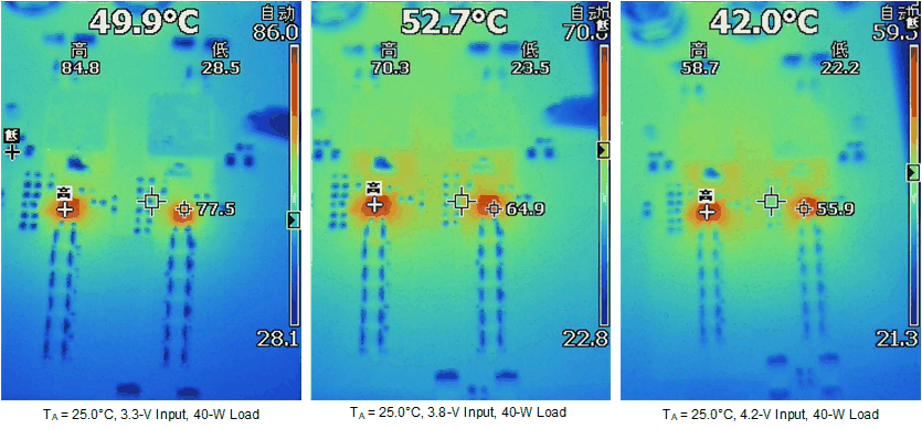
The three thermal images in Figure 2-3 illustrate the thermal conditions without current-sharing current at input voltages of 3.3 V, 3.8 V, and 4.2 V. For typical conditions, the current through the two devices is close to each other even though there is no specialized current-sharing circuit. The thermal performance at 4.2-V input is much better, this means the output power capability at 4.2-V input is more than 40 W.
 Figure 2-3 Thermal Images Without Current Sharing
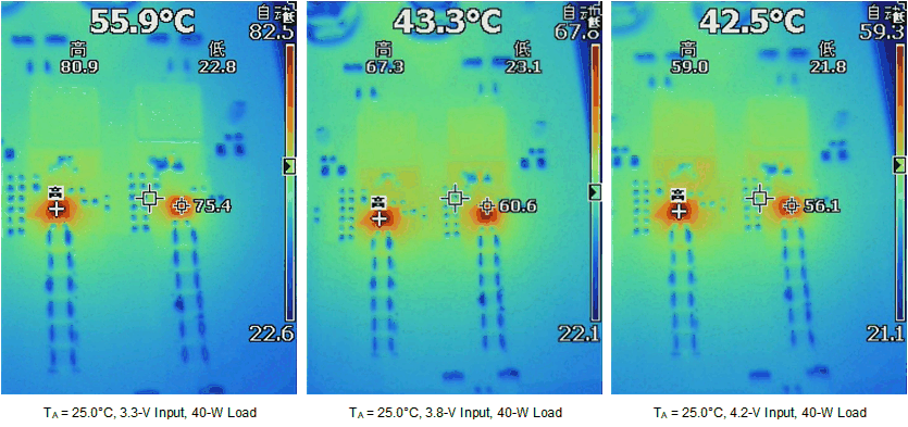
The three thermal images in Figure 2-4 illustrate the thermal conditions with an external amplifier current-sharing current.
 Figure 2-4 Thermal Images With Current Sharing