TIDT184 December 2021
1.3 Test Setup
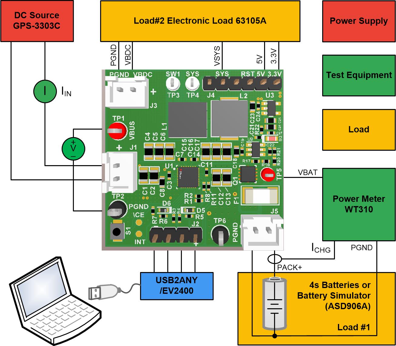
Use the following list to set up the PMP40937 test equipment:
- Connect a DC source to J1, set the output voltage to 17-V and current limit to 3-A, and then turn off the supply.
- Connect a voltage meter across TP1 (VBUS) and TP2 (PGND) to measure the input voltage.
- Connect a current meter between the DC source and TP1 to measure the input current into the VBUS.
- Connect Load #1 to J5, set Load #1 to constant voltage mode, set output voltage to 16.0-V, current limit to 3-A. A 470-µF, 25-V capacitor is recommended to add to the output if using the battery simulator.
- Connect a power meter between TP5 and J5 to measure the battery voltage and charging current.
- Set Load #2 to constant current mode, and then disable the load. Connect Load #2 to J3 and J4.
- Connect the USB2ANY between computer USB port and J2.
- DC source and Load #1, measure and verify VSYS-PGND (TP4 and TP2) = 16.0-V ± 0.2-V.
- Launch the TI-CHARGER-GUI and select device BQ25672, connect the hardware if not connected.
 Figure 1-1 Test Setup