SSZTD09 November 2023 LM25180 , LM25183 , LM25184 , LM5180 , LM5181 , LM5185 , TLV431
There has been a significant increase recently in the use of silicon carbide (SiC) field-effect transistors (FETs) in traction inverter designs. The fact that SiC inverters can produce high transient voltage (dv/dt) signals greater than 100 V/ns raises concerns for common-mode transient immunity (CMTI), representing a new challenge when designing an inverter gate driver isolated bias supply design.
Among isolated bias supply topologies, the primary-side regulated (PSR) flyback converter has the best cost-to-performance ratio given its low count of external components, tight output voltage regulation, no need for an optocoupler, high efficiency and reliable galvanic isolation. There is an effective CMTI mitigation method that can help improve PSR flyback immunity in a SiC inverter, enabling the PSR flyback’s continued use in SiC FETs and isolated bias supplies.
Using a PSR flyback as an isolated bias supply
Figure 1 shows the PSR flyback converter topology in traction inverter applications using TI’s LM5180 converter. PSR flyback devices such as the LM5181, LM25180, LM25183, LM25184 converters and the LM5185 controller, all share a common architecture with the LM5180; the main differences are in their power capabilities.
Figure 1 shows only two output rails biasing one high-side driver of the inverter’s SiC FETs. It is possible to add additional isolated outputs by coupling more windings to the transformer. The components represented dashed lines are optional for additional features.
 Figure 1 PSR flyback bias supply for
traction inverters
Figure 1 PSR flyback bias supply for
traction invertersUnlike a conventional flyback converter, which typically requires an optocoupler and a voltage reference such as the TI TLV431 on the secondary side to form the feedback circuit for tight output regulation, the PSR flyback converter senses the output voltage through the transformer’s primary winding and achieves tight output voltage regulation of the isolated voltage rail, all without the need for an optocoupler or secondary feedback circuit. This results in a simple bias-supply solution with a high cost-to-performance ratio.
Specifically, Equations 1 and 2 determine the output voltages, assuming that Vo1 is the main output (higher power):
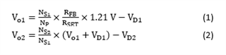
where 1.21 V is the reference voltage of the converter IC; NP, NS2 and NS2 are the number of turns of the corresponding transformer windings; RFB and RSET are the output voltage sensing and regulation setting resistors, respectively; and VD1 and VD2 are the forward voltage drop of the two output diodes.
RSET is usually fixed at 12.1 kΩ for the LM5180, LM5181, LM5183 and LM5184, and at 10 kΩ for the LM5185. Therefore, you could rewrite Equation 1 as:
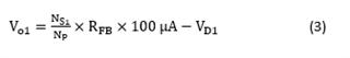
Equation 3 reveals that the output voltages remain stable if the 100-µA working current through RFB is unaffected by noise.
The challenge of CMTI
As Figure 2 illustrates, when SiC FETs switch within a few nanoseconds, the switch node of the inverter leg, which is also the SiC FET driver floating ground, will swing at a slew rate of >100 V/ns.
 Figure 2 CMTI in the standard PSR
flyback bias supply
Figure 2 CMTI in the standard PSR
flyback bias supplyThe floating ground’s high dv/dt swing is a CMT for the isolated bias supply. Figure 2 also shows how the CMT will induce CMT currents to flow through the transformer’s parasitic capacitors (represented by the dashed line) into the primary side. Part of this CMT current will flow through RFB and affect stable operation.
Figure 3 shows typical waveforms of a regular PSR flyback suffering from CMTI, captured on the standard LM5180EVM-S05 evaluation module (EVM). The yellow trace is the SiC leg’s CMT. The red trace is the PSR flyback’s SW pin voltage.
Let’s explain the intermittent switching behavior. When the CMT falls into the time window of the PSR flyback’s output sample-and-hold interval, that affects the feedback signal because the CMT current is affecting the 100-µA operating current from Equation 3. The affected feedback signal leads the converter to erroneously move away from stable operation, causing intermittent switching and interrupting steady power transfer to the output. The output voltage may dip, which in turn affects SiC inverter operation.
") Figure 3 PSR flyback affected by CMT
(vertical: channel 1 = 100 V/div, channel 2 = 10 V/div; horizontal: 50
µs/div)
Figure 3 PSR flyback affected by CMT
(vertical: channel 1 = 100 V/div, channel 2 = 10 V/div; horizontal: 50
µs/div)CMTI mitigation in the PSR flyback
Figure 4 shows the proposed CMTI mitigation method. It introduces a resistor (R1) placed in series with RFB, and a ceramic capacitor (C1) placed across the joint of the two feedback resistors and VIN pin. The resistor-capacitor forms a low-pass filter, attenuating the CMT current’s effects on the RFB’s 100-µA operating current. The optional second filter capacitor (C2, placed at the RSET pin) can also enhance the mitigation.
 Figure 4 CMTI mitigation in a PSR
flyback
Figure 4 CMTI mitigation in a PSR
flybackFigure 5 illustrates the operating principles of the CMTI mitigation method. The relative sizes of the arrows represent relative CMT current magnitudes in different paths. You can see in the feedback signal that the CMT current effects are greatly reduced.
 Figure 5 CM current attenuation at the feedback signal under CMTI mitigation in a PSR flyback
Proof of concept
When verifying the proposed CMTI mitigation method on several TI PSR flyback converter boards, including the LM5180EVM-S05 and LM5185EVM-SIO, they all demonstrated the expected improvements. Figure 6 is a schematic markup of the LM5180EVM-S05 with the method.
 Figure 6 LM5180EVM-S05 modification with CMTI mitigation
Figure 7 shows EVM performance with the CMTI mitigation method. Under the same operating conditions as Figure 3, converter operation is greatly improved, with no obvious interruptions. We observed similar improvements on the LM5185EVM-SIO.
") Figure 7 LM5180EVM-S05 performance with
CMTI mitigation (vertical: channel 1 = 100 V/div, channel 2 = 10 V/div;
horizontal: 50 µs/div)
Figure 7 LM5180EVM-S05 performance with
CMTI mitigation (vertical: channel 1 = 100 V/div, channel 2 = 10 V/div;
horizontal: 50 µs/div)Conclusion
With the proposed CMTI mitigation method, the PSR flyback will continue to be a compelling and suitable solution as the isolated bias supply, not just for SiC inverters but for applications such as onboard chargers, battery management systems and high-power DC/DC converters that employ SiC FETs.