SSZTCD2 august 2015 LMX2571 , LMX2571-EP
Have you ever done a phase-locked loop (PLL) design with a fractional synthesizer that looked great at integer channels, but then the spurs got much higher on frequencies that were just slightly offset from those integer channels? If so, you have experienced the integer boundary spur, which occurs at an offset from the carrier equal to the distance to the closest integer channel.
For instance, if the phase-detector frequency is 100 MHz and the output frequency is 2001 MHz, the integer boundary spur would be 1 MHz offset. In this case, 1 MHz might be tolerable. But when the offset gets too small, but is still nonzero, the fractional spurs are worse.
Integer Boundary Spur Reduction Using a Programmable Input Multiple
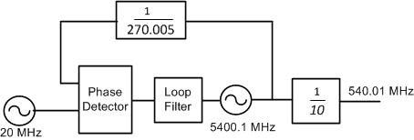
The concept of the programmable multiplier is to shift the phase detector frequency so that the voltage-controlled oscillator (VCO) frequency is far from an integer boundary. Consider a 20-MHz input frequency used to generate an output frequency of 540.01 MHz, as shown in Figure 1. The device has an output divider after the VCO, but both the output frequency and the VCO frequency are close to an integer multiple of 20 MHz. This setup would stress any PLL for fractional spurs.
 Figure 1 Integer Boundary Spur
Example
Figure 1 Integer Boundary Spur
ExampleIf the device has a programmable input multiplier, then the configuration shown in Figure 2 is possible.
 Figure 2 Avoiding Integer Boundaries
Using a Programmable Multiplier
Figure 2 Avoiding Integer Boundaries
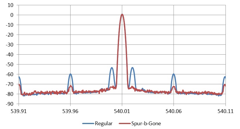
Using a Programmable MultiplierFigure 3 shows the impact of the internal multiplier. Integer boundary spurs have multiple mechanisms, and it is difficult to completely eliminate them. But this method both reduces the integer boundary spur as well as other spurs that spawn from it.
The “spur-b-gone” trace in Figure 3 shows the impact of using this programmable multiplier. There is an approximate 9-dB reduction in the integer boundary spur at 100 kHz, while substantially reducing other spurs at 50 kHz and 10 kHz.
 Figure 3 Spur Comparison with and
without Programmable Multiplier
Figure 3 Spur Comparison with and
without Programmable MultiplierThe examples shown were done with the TI’s LMX2571 synthesizer, which includes a programmable multiplier that requires no external components. This device also features 39-mA current consumption, a PLL figure of merit of –231 dBc/Hz, and a continuous output frequency range of 10–1344 MHz. It can support applications including land mobile radios, software-defined radios and wireless microphones.
Additional Resources
- View the datasheet for the LMX2571.
- Watch the demonstration video for the LMX2571.
- See TI’s entire portfolio of high-performance, low-jitter clock and timing ICs.