SSZTAP7 october 2016 CC2650 , TPS62122 , TPS62125
To unleash the full potential of Industry 4.0, factories and plants will need to be covered by sensors.
The sheer number of sensors would make wired installations prohibitive, so wireless technologies like wirelessHART and the upcoming Bluetooth® low energy mesh are immediate considerations. The cost of battery replacements for those sensors is often underestimated, however.
Instead of using batteries, powering a sensor from the signal that it is monitoring is a solution for scalability. For example, position or proximity sensors are powered by the actual motion they are monitoring, which enables the system to reach the highest level possible of predictability and robustness.
TI has released a new reference design, the Energy Harvesting for Wireless Switch Power Reference Design, which offers a power management solution for energy harvesting switches (Figure 1). The energy harvesting switch is built like a linear dynamo, transforms mechanical energy into electrical energy. The reference design harvests this electrical energy to enable wireless position control of valves or other mechanical actuators, as well as emergency switches and controllers for machine starts and stops.
 Figure 1 Energy Harvesting for Wireless
Switch Power Reference Design
Figure 1 Energy Harvesting for Wireless
Switch Power Reference DesignThe reference design’s application spans factory automation and process control to building automation, as well as nonindustrial areas. You can use this type of solution when you need lower maintenance and installation costs, higher system uptimes and increased flexibility – and when wiring is considered infeasible. In addition, due to the design’s inherent low-power operating characteristics, it is an optimal solution for explosive-proof applications, avoiding the use of expensive protection methods.
When designing an energy-harvesting circuit, the challenge is to extract the maximum amount of energy regardless of the load to have a flexible design reusable across multiple systems.
An electrodynamic system can be a generator with a fixed-output impedance, so in theory, to maximize the energy extraction, you only have to match the source impedance with the load. However, for a dynamically behaving load, this is not possible.
An alternative is to buffer the energy so it can be given as a constant supply to the active load. The challenge is then to be able to still extract as much energy from the generator without exposing a constant load. Two main things should be considered:
- By leaving the input cap of the DC/DC charge for as long as possible, no energy is extracted as soon as the output voltage of the generator goes below the voltage of the input cap.
- By enabling the DC/DC to start as soon as possible, the generator is operating as close as possible to its short-circuit operating point, which is also further away from its maximum power point.
Another design consideration to keep in mind is that the generator will generate two pulses: one positive and one negative for each full actuation (push and release). The reference design maximizes energy extraction by going for the rectification of the negative wave.
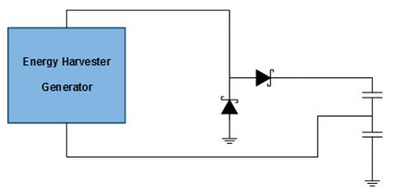
For the rectification, two options are possible: either a full-wave rectification or a voltage doubler. The reference design follows the voltage-doubler (see Figure 2) option for two reasons:
- A voltage doubler has only half of the diode losses compared to a full-wave rectifier, so the overall efficiency increases.
- The energy left in a cap when the DC/DC reaches its undervoltage lockout (UVLO) can be considered lost. With a full-wave rectifier, this is always the case. With a voltage doubler, the second wave will charge the cap on top of the UVLO level and thus will be fully used.
Finally, the input-cap value as a function of the UVLO voltage was optimized through trial and error with the goal of maximizing the runtime of the DC/DC (that is, the time for which it provides a valid voltage on its output).
 Figure 2 How to Extract the Maximum
Amount of Energy from the Energy Harvesting Switch
Figure 2 How to Extract the Maximum
Amount of Energy from the Energy Harvesting SwitchThe reference design easily interfaces to the SimpleLink™ CC2650 wireless MCU LaunchPad™ kit to transmit wireless data through the CC2650, powered by either the TPS62122 or the TPS62125 present on the board.
The reference design sends out non-connectable advertisement packets on three separate channels that contain 8 bytes of data.
This design could be one of your first steps to unleash your smart factory. Have a look to the schematics, layout and test data on the design page.
Additional Resources
- Watch the video, “How to harvest energy with nano-power DC/DC solutions.”
- Read this blog post, The secrets of energy harvesting: The sloth and the bear