SSZT931 october 2017 TAS6424-Q1
You can’t turn on the TV or open a website lately without seeing or reading about the tiny home craze. Smaller is supposedly better, right? Similarly, mobile phone manufacturers tout how small, slim or lightweight their next-generation phone is.
It just seems natural that this trend would spill over into the automotive audio Class-D amplifier space. So in this post, I’ll talk about how tiny inductors are used with Class-D amplifiers in infotainment systems.
Background
Automotive Class-D audio amplifier designs require a filter on the output of the amplifier. This filter uses both an inductor and a capacitor on each output terminal, usually referred to as an inductor-capacitor (LC) filter. Proper selection of the LC filter values is critical to meet the desired audio performance, efficiency, electromagnetic compatibility (EMC)/electromagnetic interference (EMI) requirements and cost, especially in automobile head unit and external amplifier applications.
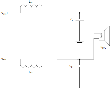
The Class-D amplifier bridge-tied load circuit shown in Figure 1 is an output configuration where the speaker (or load) is connected between two amplifier outputs, bridging the two output terminals. Automotive Class-D audio amplifiers therefore typically require two inductors per channel (speaker).
 Figure 1 Class-D Amplifier Bridge-tied
Load Circuit
Figure 1 Class-D Amplifier Bridge-tied
Load CircuitWhy Are Tiny Inductors Important?
Automobile manufacturers are adding more electronic subsystems in today’s vehicles. Yet space is at a premium, so electronic module suppliers are under pressure to make their subsystems smaller. A secondary effect is that automobile manufacturers are continuously striving to make vehicles lighter weight to increase fuel efficiency. While there are many subsystems to evaluate, today I’d like to focus on comparing inductor sizes and weight as part of car radio designs within an infotainment system.
A typical car radio design has at least four channels to drive two front speakers and two rear speakers. This simple configuration would require eight total inductors for a Class-D automotive audio amplifier, since each channel requires two inductors, as shown in Figure 1. Thus, the size of each inductor is multiplied by eight, which is a significant contribution to overall printed circuit board (PCB) size and design weight.
Inductor Size vs. Amplifier Switching Frequency
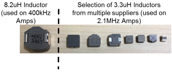
For Class-D automotive audio amplifiers, the value of the inductor required in the LC filter to ensure the proper pulse-width modulation (PWM) demodulation filter characteristic depends on the switching frequency. In Figure 2, the inductor size used in LC filters for a typical Class-D audio amplifier design that switches around 400kHz are quite a bit larger and bulkier than those required for a newer Class-D amplifier design switching at a much higher frequency, such as 2.1MHz on TI’s TAS6424-Q1 device.
A 400kHz automotive audio amplifier typically uses either a 10µH or 8.2µH inductor value, while the 2.1MHz higher-switching-frequency amplifier design can take advantage of a much smaller and lighter-weight inductor in the range of 3.3µH to 3.6µH (assuming that each amplifier provides equivalent output power).
 Figure 2 Comparison of Inductor Size
vs. Switching Frequency
Figure 2 Comparison of Inductor Size
vs. Switching FrequencyWhat Drives Inductor Weight?
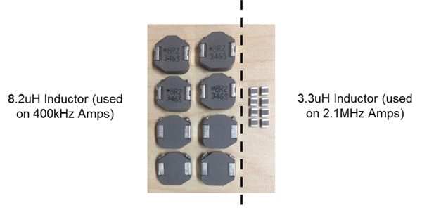
The weight difference between 8.2µH and 3.3µH inductors is mainly caused by the sheer difference in the weight of the copper windings and core material required to achieve the LC filter’s required inductance value and current-handling capability. As previously mentioned, a simple four-channel car radio design requires eight total inductors. In Figure 3, you can see the difference in weight (the total weight of copper and core material) of a four-channel radio design based on a 400kHz switching frequency versus one based on a 2.1MHz switching frequency.
 Figure 3 Inductor Weight Differences
for a Typical Four-channel Amplifier
Figure 3 Inductor Weight Differences
for a Typical Four-channel AmplifierNewer Metal-alloy Inductors Enable Very Small Amplifier Size
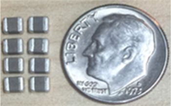
Inductors used in 400kHz switching frequency amplifier designs are traditionally made using copper wire and ferrite materials for the core. With the implementation of the higher 2.1MHz switching frequency, it’s possible to develop inductors with copper wire and a new metal-alloy core technology, which enables incredibly tiny inductor sizes. Figure 4 shows that the newer metal-alloy technology not only provides the lightest weight solution, but helps greatly reduce the overall solution size for a four-channel amplifier.
 Figure 4 Tiny Metal-alloy Inductors for
a Typical Four-channel Amplifier
Figure 4 Tiny Metal-alloy Inductors for
a Typical Four-channel AmplifierConclusion
Higher-switching-frequency automotive Class-D audio amplifier designs, like the 2.1MHz TAS6424-Q1, are the way of the future to fulfill industry demands for next generation car radios and external amplifiers. The higher-switching-frequency amplifiers also help to drive technology advancement in the inductor industry, thereby helping to provide overall smaller and lighter weight system solutions. Want to know more about LC filter design? Download this application report for in-depth design information.
Additional Resources
- Order the TAS6424-Q1 evaluation module to hear the outstanding sound quality from TI’s higher-switching-frequency automotive Class-D solution using 3.3µH inductors.
- Download the TAS6424-Q1 data sheet.
- Check out the application report “TAS6424-Q1 Inductor Selection Guide”.