SSZT858 December 2017 ESD122
In the second installment of this series, I went over the basics of the International Electrotechnical Commission (IEC) 61000-4-2 rating for electrostatic discharge (ESD) diodes.
One comment that I frequently hear from circuit designers after an ESD failure is, “I used an ESD protection diode that was rated for 30kV contact and 30kV air-gap IEC 61000-4-2 ESD. Why did my system still fail? A 30kV/30kV rating is way above the recommended 8kV/15kV rating!”
While the IEC 61000-4-2 rating is important, it is not the only factor that you need to consider when selecting an ESD diode. The IEC 61000-4-2 rating only tells you how much voltage the ESD diode itself can withstand. The rating gives no indication of whether the downstream circuitry will be protected. To understand that, you would need to look at the clamping voltage of the diode.
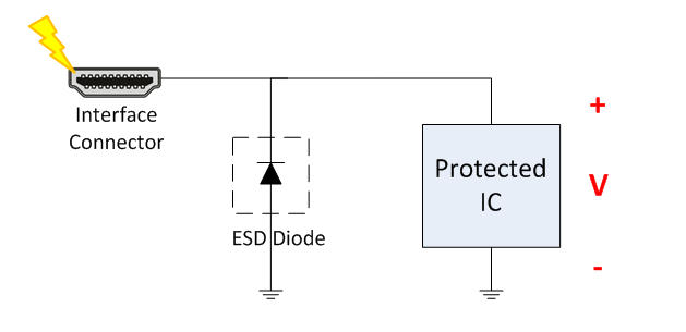
A protection diode placed in parallel with the circuit protects that circuit from ESD. When an ESD strike occurs, the diode will promptly break down and steer “all” of the ESD current to ground, thus protecting the circuit downstream. I put “all” in parentheses because the only way all of the ESD current would flow through the ESD diode is if the diode had zero impedance. In the real world, all ESD diodes have some small resistance, called the dynamic resistance (RDYN). RDYN will cause a voltage drop across a conducting diode; since the protected integrated circuit (IC) is in parallel, you will see that same voltage drop across the protected IC (Figure 1). This voltage drop is known as the clamping voltage.
 Figure 1 Clamping Voltage of an ESD
Diode
Figure 1 Clamping Voltage of an ESD
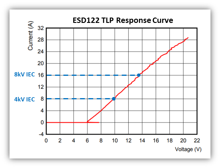
DiodeThe clamping voltage of an ESD diode will ultimately determine whether or not a downstream IC will be protected against ESD strikes. Although it is one of the most important specifications, it is also probably the hardest to find on a data sheet. The easiest way to determine the true clamping voltage of a diode when exposed to an IEC ESD strike is to look at the transmission line pulse (TLP) response curve. Figure 2 is an example of the ESD122 TLP response curve, which shows the device’s relationship between current and voltage. As you can see, when the current flowing through the device increases, the voltage across the device increases at an almost linear rate.
 Figure 2 TLP Response Curve for the
ESD122
Figure 2 TLP Response Curve for the
ESD122The TLP is useful because it has similar characteristics to an IEC 61000-4-2 ESD strike. As a result, you can correlate TLP current with IEC ESD:
- A 2kV IEC strike = 4A TLP.
- A 4kV IEC strike = 8A TLP.
- A 6kV IEC strike = 12A TLP.
- A 8kV IEC strike = 16A TLP.
With this information, you can extrapolate from the TLP response curve in Figure 2 that the ESD122 will have a clamping voltage of ~13.5V during an 8kV IEC 61000-4-2 ESD strike. In other words, you can expect the downstream circuit to be exposed to 13.5V for approximately 100ns when an 8kV IEC strike occurs.
As a general rule, the lower the clamping voltage, the better the protection performance, so look for the TLP curve the next time you select an ESD diode. Read part four of the ESD Fundamentals technical article series, "ESD fundamentals, part 4: ESD capacitance, where we go over the significance of the ESD protection diode’s capacitance."
Additional Resources
- View all articles in the ESD Fundamentals technical article series.
- For more information about TI’s low clamping solutions, check out he application report, “Picking ESD Diodes for Ultra High-Speed Data Lines.”
- Read the application brief, "High-Speed Layout Guidelines for Signal Conditioners and USB Hubs."