SSZT477 may 2019 ISO7021 , ISO7041
What keeps chocolate factories, oil refineries and water treatment plants operating successfully? It’s automated machinery, which has the ability to sense, measure and react during every step of a designated process.
Field transmitters give factories a way to automate the sensing, measuring and communicating of critical system vitals such as temperature, pressure and flow. Some estimates indicate that more than 100 million field transmitters are shipped out annually in order to support industrial applications worldwide. Without the measurement output from field transmitters, factory automation would not be as accurate or reliable – limiting its effectiveness.
Before exploring the importance of field transmitters and their design challenges, let’s briefly define field transmitters.
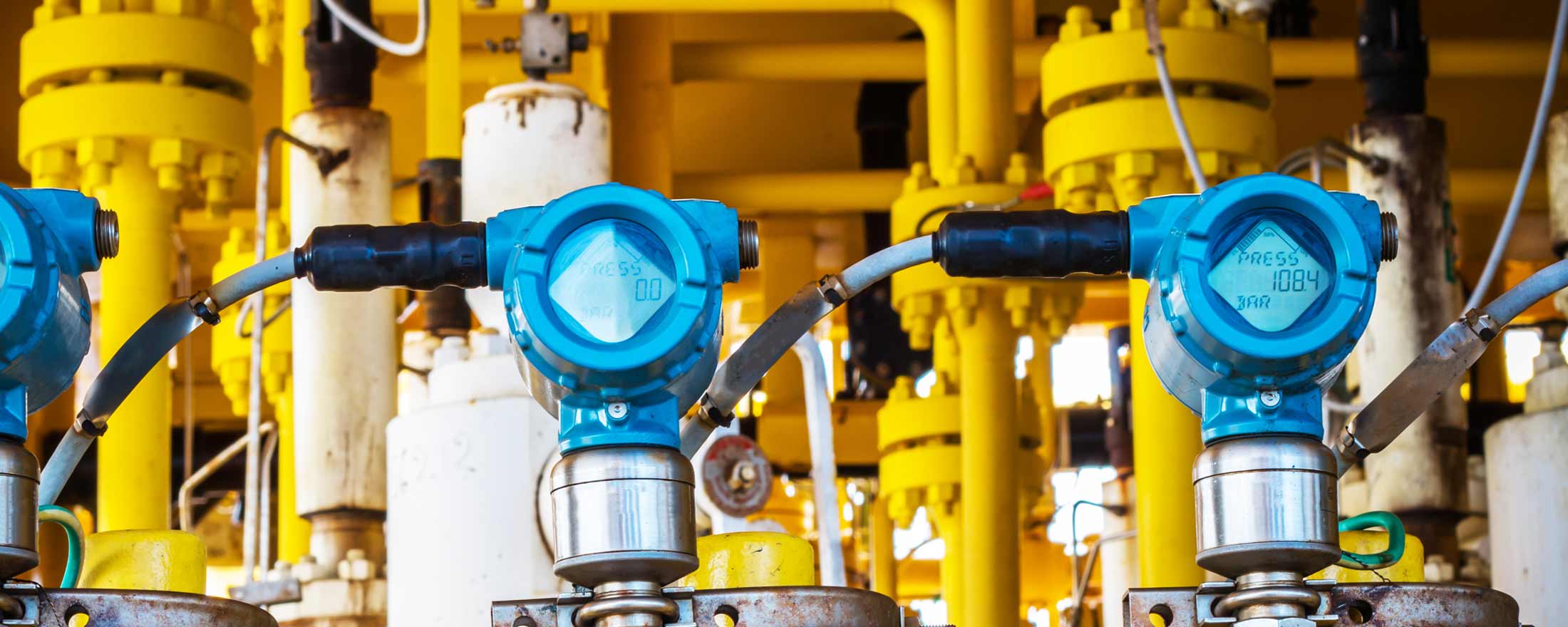
 Figure 1 Pressure Transmitters
At a basic level, a field transmitter is a device that uses sensors to measure and communicate information about the surrounding environment (temperature, pressure, flow, etc.) This device converts its measurements into a readable electrical signal and then transfers data across long lengths of cable to a centralized device capable of processing the information and calculating next steps. One of the more common field transmitter architectures, frequently referred to as two-wire or loop-powered systems, operates on a 4- to 20-mA bus and is the focus of this article.
Field Transmitter Power Considerations
Field Transmitter Design Challenges
To overcome this challenge, the addition of an isolation barrier between the sensor and current loop enables independent grounding of both the sensor and the receiver, eliminating unintentional ground loops.
Isolating on a Power Budget
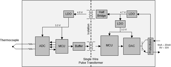
 Figure 2 Field Transmitter Example - Single-channel Pulse Transformer for Data Isolation
Despite their many advantages, digital isolators historically had little to no use in field transmitter designs because the amount of current they consumed was outside the budget requirements. But major advancements in digital isolator technology, such as reduced power consumption, have enabled key field transmitter system improvements. For example, TI’s ISO7041 ultra-low-power digital isolator can consume as little as 4.2 µA per channel in quiescent operation.
Some of the advantages, which are discussed in further detail in the application note "How to Isolate Two-Wire Loop-Powered Field Transmitters," include:
- Ultra-low-power scalability. Total power consumption under 20 µA at 10 kbps provides significant power back to the system and enables other system improvements that were historically impossible to accomplish within the power budget.
- Increased data rate/throughput. Data rates up to 2 Mbps enable data-transfer improvements between the sensor and the transmitter.
- Wider temperature ranges. Extended temperature ranges from -55°C to 125°C can enable transmitter use in extreme conditions without the need to source higher-temperature-rated, higher-cost optocouplers.
- Reduced solution size. Higher channel counts in less than half the area, along with reduced height requirements, lead to more compact designs and reduced printed circuit board cost.
- Improved reliability and predictability. Highly controlled semiconductor processes provide reliable isolation with well-defined industry-standard isolation barrier lifetimes and much lower device-to-device variation compared to optocouplers.
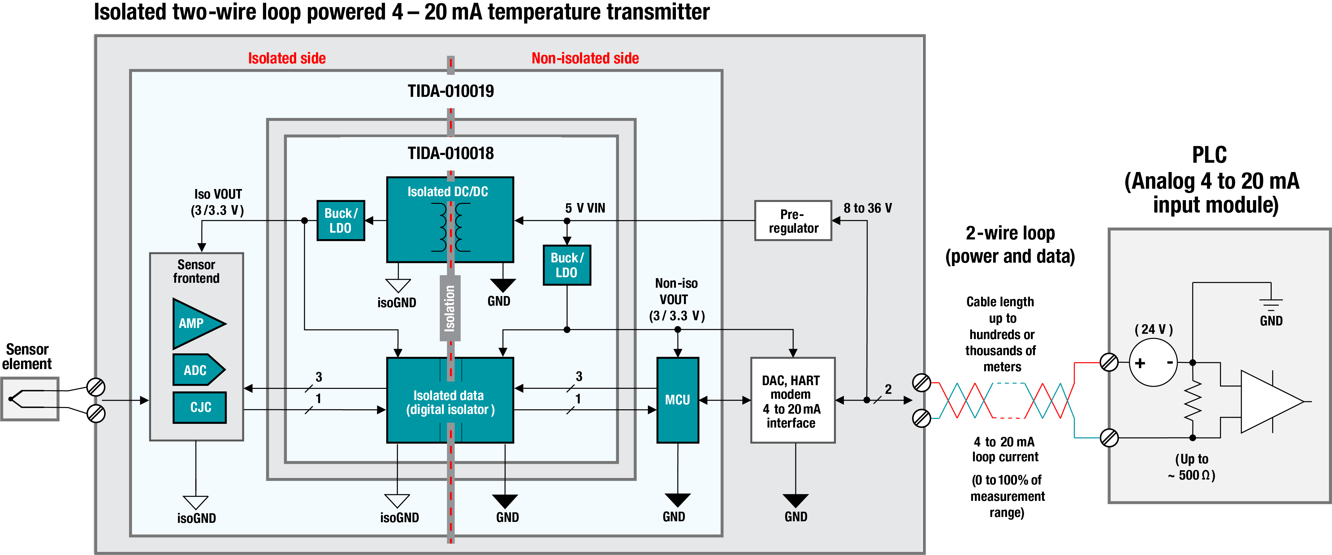
For a head start on an isolated 4- to 20-mA design, the TI reference designs Isolated Power and Data Interface for Low-Power Applications Reference Design and RTD Replacement for Cold Junction Compensation in a Temperature Sensor Reference Design provide an isolated temperature transmitter design with TI’s latest devices. Figure 3 is a block diagram showing both designs working together.
 Figure 3 Isolated Temperature Transmitter Reference Design Block Diagram
The need for precise and abundant sensor measurements is why field transmitters are critical to running intelligent and safe processes in the world of factory automation. While reducing overall system cost continues to drive the need for low-power two-wire solutions, times have changed, and digital isolators such as the 4 channel ISO7041 and 2 channel ISO7021 can improve reliability and enhance features while sticking to power and cost budgets. As automation continues to expand and improve, no stone must go unturned in order to increase throughput, improve consistency, and reduce cost and energy.
Additional Resources
- Explore our growing portfolio of digital isolators.
- Learn more about our factory automation and control solutions.