SSZT460 june 2019 INA185 , INA301 , INA301-Q1 , TLV4021
The electrification of vehicles is occurring not only in powertrain systems such as traction inverters, battery management and electric power steering, but also in automotive safety systems such as anti-lock brake systems or automated driving. Knowing that these systems are operating within the correct operational guidelines will be vital to helping ensure vehicle safety. Accurate measurement of current and a fast fault response time are critical to enabling debugging and diagnostics in these systems.
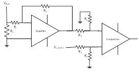
Figure 1 shows a typical overcurrent circuit consisting of a discrete operational amplifier and a discrete comparator.
 Figure 1 Overcurrent Detection
Implementation Featuring a Discrete Operational Amplifier and Comparator
Figure 1 Overcurrent Detection
Implementation Featuring a Discrete Operational Amplifier and ComparatorSeveral sources will determine the accuracy and response time of this system, including:
- Shunt resistor (RS) tolerance and drift.
- Amplifier circuit gain error (RI and RF).
- Voltage divider (R1 and R2) error between the amplifier and comparator.
- Comparator reference (R3 and R4) input error.
- The amplifier circuit’s response time.
- The comparator’s response time.
The errors caused by the shunt, gain and divider between the amplifier and comparator all contribute to a worst-case current measurement error. Depending on this error level, you will have to build margin into your design to ensure that it does not exceed the required operating parameters.
Learn in our white paper how overcurrent protection enables longer lifecycles.
The total fault condition response time includes not only the amplifier and comparator response times; you must also take into account microcontroller (MCU) cycle time as well as the protection circuit’s turn-on and turn-off times. The total response time must be less than what is required to bring the system to a safe operating condition. Typically, the MCU cycle time and protection circuit are fixed; therefore, you’ll have to adjust the amplifier and comparator response times to meet the system requirements. TI offers a wide range of solutions with various response times for amplifiers and comparators.
If you want to improve the current-sensing accuracy, using higher-precision lower-drift resistors with the circuit shown in Figure 1 is one option; however, as the accuracy and drift of the external components increases, so does the cost. An alternative is to use a current-sense amplifier such as the TI INA185. Current-sense amplifiers integrate a precision matched-resistor gain network that cost-effectively reduces the gain error as well as the drift. In the case of the INA185, the gain error is ±0.25% with 8 ppm/°C drift, or ±0.33% over temperature.
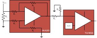
It is also possible to improve the reference error by using better resistors. Using a comparator with an integrated precision reference such as the TI TLV4021 can also offer significant improvement, with ±0.04% error over temperature. Figure 2 shows a circuit that uses both the INA185 and TLV4021 for an overcurrent detection circuit.
 Figure 2 Overcurrent Detection
Implementation Featuring a Precision Current-sense Amplifier and Precision
Comparator
Figure 2 Overcurrent Detection
Implementation Featuring a Precision Current-sense Amplifier and Precision
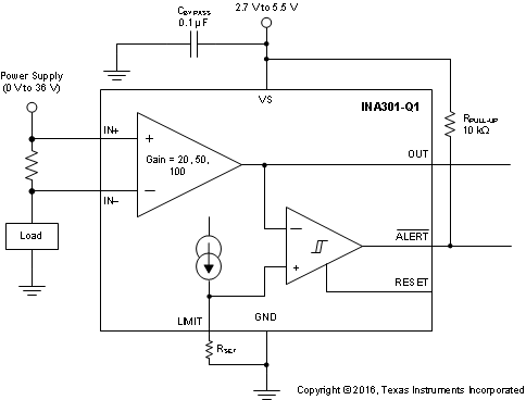
ComparatorThis leaves divider error as the primary error source. You can eliminate this error source by using a current-sense amplifier such as the TI INA301, which integrates the comparator and a precision reference, as shown in Figure 3.
 Figure 3 INA301 Functional Block
Diagram
Figure 3 INA301 Functional Block
DiagramThe INA301 has a precision current source on-chip that requires only a single external resistor to set the threshold. In addition, the total response time for the alert output is less than 1 µs.
Monitoring a system’s current provides a leading indicator of potential issues. Increasing the accuracy of your overcurrent detection implementation can improve system power efficiency by minimizing the allocated headroom. There are many overcurrent detection solutions that can be optimized based on the key concerns of a particular application: cost, solution size, accuracy, or response time. You can trade off the low cost of typical discrete implementations with the increased precision offered by current-sense amplifiers and comparators with integrated references.
References
- Download the TLV4021 data sheet.
- Download the INA301 data sheet.
- Getting Started with Current Sense Amplifiers, Texas Instruments Training Series