SSZT245 october 2020 TMUX1108 , TMUX1511
When designing reliable servo drive control modules, both precision and protection are critical for ensuring reliable operation. Underestimating the importance of these features in the design process could lead to incorrect readings or damages to the analog-to-digital converter (ADC) or microcontroller, thus lowering system efficiency or leading to downtime.
Think about precision and protection like penalty kicks in soccer, where more precise shooting or better protection from the goalkeeper can make the difference between a victory and a loss.
When a servo drive has hot-side control or cold-side control, an ADC and a multiplexer are used to measure the three phases to ground voltages and the DC-link voltage. Precision is paramount so that the motor drive will have the right torque, speed, and position within a servo drive controller.
Selecting the "right" multiplexer will help prevent errors or false readings while helping to optimize system efficiency. An 8:1 one-channel multiplexer such as the TMUX1108 can provide precise data inputs to the ADC through its low on-resistance, on-capacitance and leakage currents. These features enable precise feedback to the MCU to allow for correct torque, speed and positioning for the motor drive system.
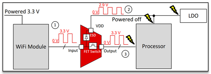
Overvoltage events are one of many situations that can cause unwanted back-powering and damages downstream in your signal chain in a servo drive control module. Applying a voltage before powering up the entire device for the digital or analog interface can also potentially provide incorrect readings or provide input voltages when the device is off. In Figure 1, the analog sensors are transmitting a 3.3-V signal to the switch input when the switch is off. The 3.3-V signal back-powers the unpowered switch through the electrostatic discharge diode, unintentionally turning the switch on.
The unwanted 3.3-V signal is then transmitted through the switch, damaging the ADC or causing an incorrect reading. Multiplexers with powered-off protection features will protect downstream components when input signals are present in the input/output (I/O) pins while the switch is unpowered, without causing any unnecessary signal degradation.
 Figure 1 3.3-V signal back-powering a
multiplexer
Figure 1 3.3-V signal back-powering a
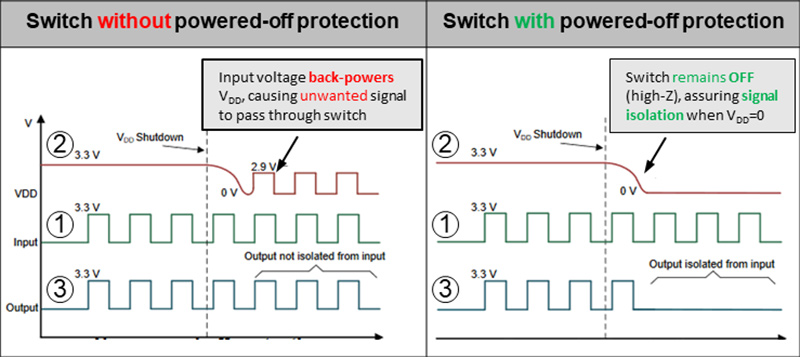
multiplexerIn Figure 2, the switch with powered-off protection maintains a high-impedance state on the I/O pins, which prevents back-powering, and the switch without powered-off protection features allows unwanted signals to pass.
 Figure 2 Signal switch with and without
powered-off protection
Figure 2 Signal switch with and without
powered-off protectionA 1:1 four-channel multiplexer such as the TMUX1511 has powered-off protection features to help ensure that the multiplexer powers up before the application of Serial Peripheral Interface signals at the inputs of a microcontroller or ADC. For more information about power sequencing with multiplexers, see the application note, “Eliminate power sequencing with powered-off protection signal switches.”
Finding the right multiplexer with protection and precision features can prevent problems from occurring within your servo drive control module or your overall system. Just like in soccer, being precise with a shot or having a lapse when trying to protect the goal can mean the difference between winning and losing a match.