SPMA041G January 2012 – October 2015 TM4C1230C3PM , TM4C1230C3PM , TM4C1230D5PM , TM4C1230D5PM , TM4C1230E6PM , TM4C1230E6PM , TM4C1230H6PM , TM4C1230H6PM , TM4C1231C3PM , TM4C1231C3PM , TM4C1231D5PM , TM4C1231D5PM , TM4C1231D5PZ , TM4C1231D5PZ , TM4C1231E6PM , TM4C1231E6PM , TM4C1231E6PZ , TM4C1231E6PZ , TM4C1231H6PGE , TM4C1231H6PGE , TM4C1231H6PM , TM4C1231H6PM , TM4C1231H6PZ , TM4C1231H6PZ , TM4C1232C3PM , TM4C1232C3PM , TM4C1232D5PM , TM4C1232D5PM , TM4C1232E6PM , TM4C1232E6PM , TM4C1232H6PM , TM4C1232H6PM , TM4C1233C3PM , TM4C1233C3PM , TM4C1233D5PM , TM4C1233D5PM , TM4C1233D5PZ , TM4C1233D5PZ , TM4C1233E6PM , TM4C1233E6PM , TM4C1233E6PZ , TM4C1233E6PZ , TM4C1233H6PGE , TM4C1233H6PGE , TM4C1233H6PM , TM4C1233H6PM , TM4C1233H6PZ , TM4C1233H6PZ , TM4C1236D5PM , TM4C1236D5PM , TM4C1236E6PM , TM4C1236E6PM , TM4C1236H6PM , TM4C1236H6PM , TM4C1237D5PM , TM4C1237D5PM , TM4C1237D5PZ , TM4C1237D5PZ , TM4C1237E6PM , TM4C1237E6PM , TM4C1237E6PZ , TM4C1237E6PZ , TM4C1237H6PGE , TM4C1237H6PGE , TM4C1237H6PM , TM4C1237H6PM , TM4C1237H6PZ , TM4C1237H6PZ , TM4C123AE6PM , TM4C123AE6PM , TM4C123AH6PM , TM4C123AH6PM , TM4C123BE6PM , TM4C123BE6PM , TM4C123BE6PZ , TM4C123BE6PZ , TM4C123BH6PGE , TM4C123BH6PGE , TM4C123BH6PM , TM4C123BH6PM , TM4C123BH6PZ , TM4C123BH6PZ , TM4C123BH6ZRB , TM4C123BH6ZRB , TM4C123FE6PM , TM4C123FE6PM , TM4C123FH6PM , TM4C123FH6PM , TM4C123GE6PM , TM4C123GE6PM , TM4C123GE6PZ , TM4C123GE6PZ , TM4C123GH6PGE , TM4C123GH6PGE , TM4C123GH6PM , TM4C123GH6PM , TM4C123GH6PZ , TM4C123GH6PZ , TM4C123GH6ZRB , TM4C123GH6ZRB , TM4C123GH6ZXR , TM4C123GH6ZXR , TM4C1290NCPDT , TM4C1290NCPDT , TM4C1290NCZAD , TM4C1290NCZAD , TM4C1292NCPDT , TM4C1292NCPDT , TM4C1292NCZAD , TM4C1292NCZAD , TM4C1294KCPDT , TM4C1294KCPDT , TM4C1294NCPDT , TM4C1294NCPDT , TM4C1294NCZAD , TM4C1294NCZAD , TM4C1297NCZAD , TM4C1297NCZAD , TM4C1299KCZAD , TM4C1299KCZAD , TM4C1299NCZAD , TM4C1299NCZAD , TM4C129CNCPDT , TM4C129CNCPDT , TM4C129CNCZAD , TM4C129CNCZAD , TM4C129DNCPDT , TM4C129DNCPDT , TM4C129DNCZAD , TM4C129DNCZAD , TM4C129EKCPDT , TM4C129EKCPDT , TM4C129ENCPDT , TM4C129ENCPDT , TM4C129ENCZAD , TM4C129ENCZAD , TM4C129LNCZAD , TM4C129LNCZAD , TM4C129XKCZAD , TM4C129XKCZAD , TM4C129XNCZAD , TM4C129XNCZAD
4.4 Building, Running, and Verifying the Project
Once the project has been created, the source code has been added to the work space, and the project properties have been properly configured, the project can be built by right clicking on it in the Project Explorer and selecting Build Project.
If this is the first time that Code Composer Studio is being used to connect to a target via the Stellaris In-Circuit Debug Interface, it might be necessary to install the proper drivers before it is possible to connect to the target to run code. Instructions for doing this can be found in the Code Composer Studiov6.1 Quick Start Guide, available at http://processors.wiki.ti.com/index.php/Category:Code_Composer_Studio_v6.
Once the code has been built and the proper drivers have been installed, you can run your code by using the following steps:
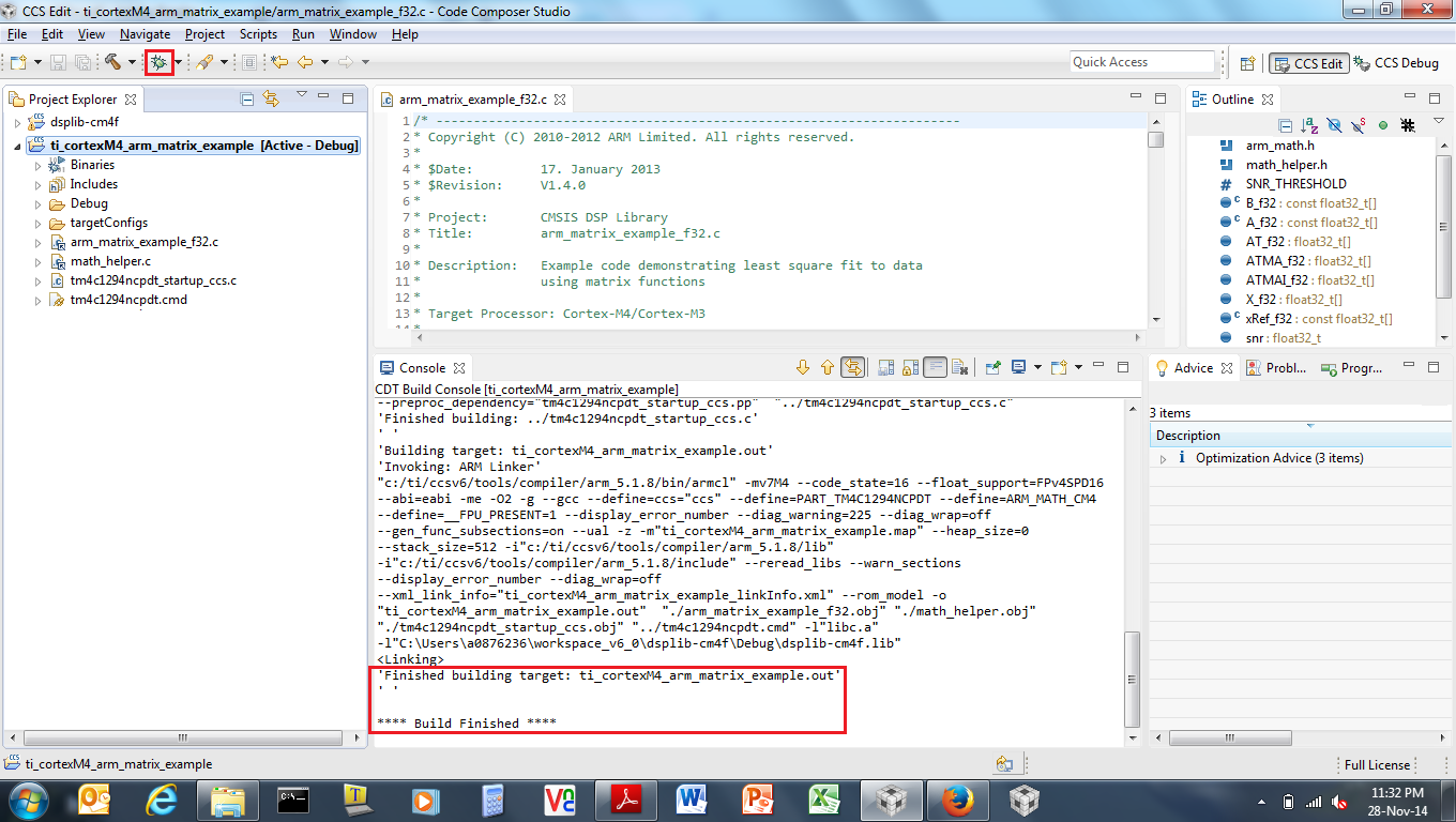
- Press the Debug icon in the Code Composer Studio toolbar (see Figure 25).
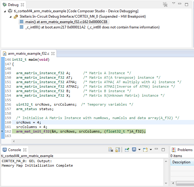
- It takes a moment for Code Composer Studio to connect to the MCU and download the code. Once the connection has been established and the flash programmed with the compiled project code, the MCU will run until it reaches the project’s main() function (see Figure 26). Press the Resume button (or F8) to cause the program to start executing.
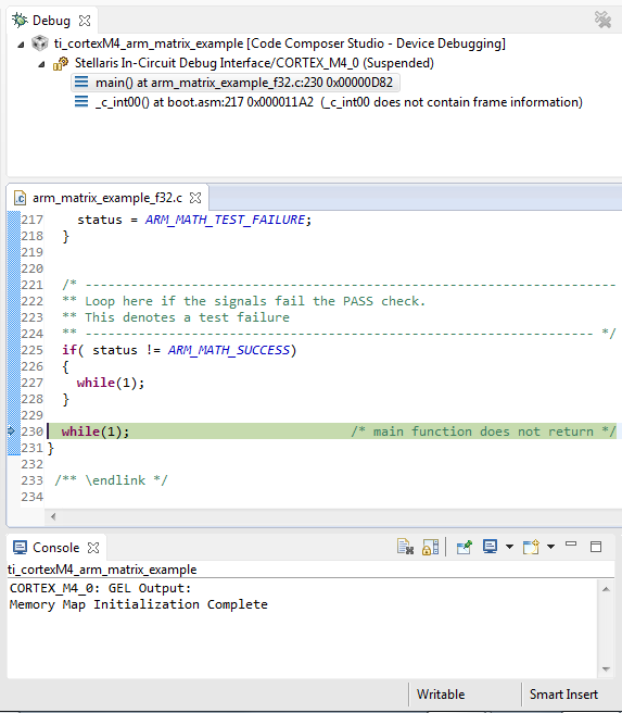
- After a few seconds have passed, the program will run to completion (see Figure 27). Press the suspend button, which will halt the processor and show you what line of code is being executed.
- For every function other than the class marks example, the program will have halted in one of two while loops. If the program did not successfully execute, it will be caught in a while loop surrounded by an if statement with a test condition of (status != ARM_MATH_SUCCESS). If the program did successfully execute, it is caught in a while loop found immediately after the previously mentioned if statement. For the class marks example, there is no built in method by which the microcontroller’s execution state can be verified.
 Figure 25. The Debug Context Being Displayed After the arm_matrix_example Project has Been Set Up for Debugging
  Figure 26. The arm_matrix_example Project, After it has Been Loaded Into Flash and the Startup Code has run to the main() Function
  Figure 27. The arm_matrix_example Project Having Run to Successful Completion