SNVU698B September 2020 – December 2020 LMQ61460-Q1
6.4 Thermals
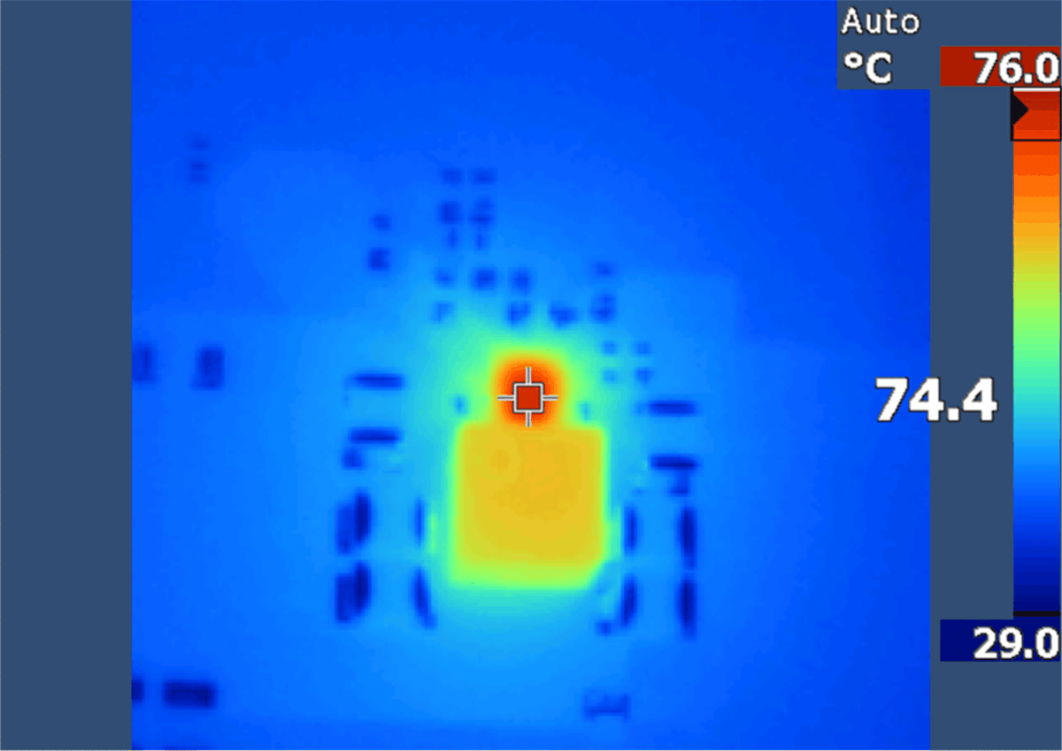
A thermal image of the IC was captured to determine rise in temp with a 5-V, 6-A load. The device was soaked for 30 minutes to obtain accurate measurement.
 Figure 6-23 Thermal Image Capture of IC at VIN = 13.5 V, VOUT = 5 V, Load = 6 A
Note:
Thermal image captures top of case temperature. This is essentially junction temperature as the case package is very thin, resulting in low psi-jt. This demonstrates device capability of operating greater than 85°C ambient with headroom.