SNOU172 December 2020 LM74500-Q1
2.2 Board Setup
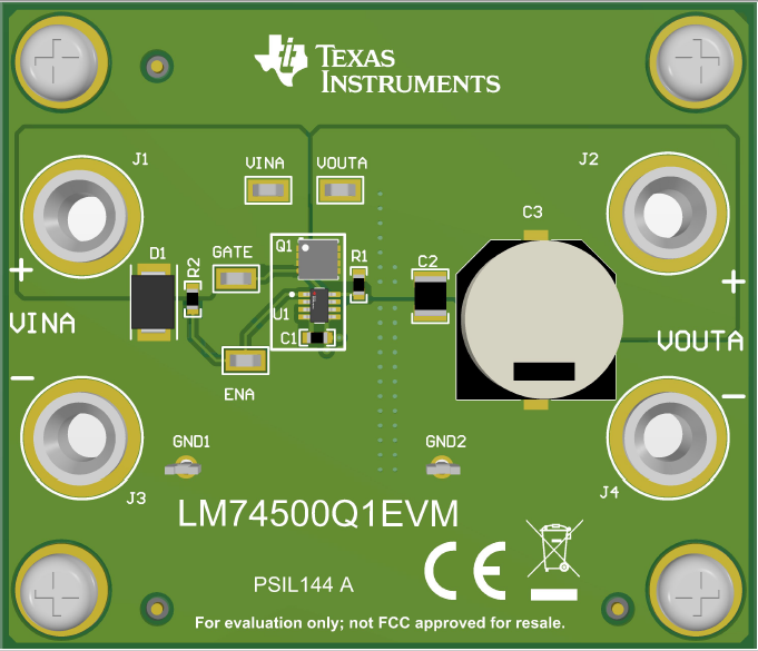
Before applying power to the LM74500Q1EVM, verify all external connections. Turn off external power supplies and connect them with the proper polarity to the VIN and GND1 connectors. An electronic or resistive load must be connected at the output VOUT and GND2 connectors. The tests outlined in this document are conducted with 3-A constant current as the load and 12 V at the input. Make sure that the external power-supply source for the input voltage is capable of providing enough current to the output load so that the output voltage can be obtained.
When all connections to the LM74500Q1EVM are verified, apply power to VIN. Figure 2-2 captures EVM board setup.
 Figure 2-2 LM74500Q1EVM