SNOAA76 August 2021 LDC3114 , LDC3114-Q1
2.1 Target Properties
To achieve the best sensing response, the metal target should be at least the size of the sensing coil. It is also important to choose a highly conductive metal, such as copper or aluminum, because these have stronger inductive responses.
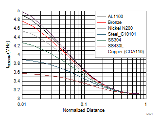
Figure 2-1 shows the sensor frequency shift of several common metals as a function of distance. Any discontinuities in the metal (gaps, voids, or indents) should be avoided, as they can cause disruptions in the current path and lead to measurement noise.
 Figure 2-1 Sensor Frequency vs Distance of
Common Targets
Figure 2-1 Sensor Frequency vs Distance of
Common TargetsIn regards to target thickness, it is a general guideline that it should be at least 3 skin depths. Skin depth, δ, is the distance where the eddy currents are reduced to approximately 37% of the density at the surface.
For further details on target design and calculating skin depth, refer to the LDC Target Design application report.