SNLA236 September 2015 DS125BR111 , DS125BR401A , DS125BR820
4.2 Channel Extension
In order to assess channel extension in a system environment, a PCB with the DS125BR401A and miniSAS-HD connectors was developed.
 Figure 7. SAS-3 System Test Setup
 The following EQ, VOD, DEM, and VOD_DB settings have been tested for SAS-3 12 Gbps operation with a SAS-3 Expander ASIC. The cable lengths tested ranged from 1 – 12 meters with no more than 7 meters on one side of the DS125BR401A. The test data is shown in the table below.
Table 4. DS125BR401A Settings Used for Testing
| CABLE LENGTHS | DS125BR401A SETTINGS | BER Testing Result | ||||||
|---|---|---|---|---|---|---|---|---|
| Cable1 | Cable 2 | CH-A
EQ |
CH-A
VOD |
CH-A
DEM |
CH-B
EQ |
CH-B
VOD |
CH-B
DEM |
|
| 2m | 7m | 0x03’h | 110’b | 0x00’h | 0x03’h | 1.4Vpp | 0x00’h | Pass |
| 3m | 7m | 0x03’h | 110’b | 0x00’h | 0x03’h | 1.4Vpp | 0x00’h | Pass |
| 5m | 7m | 0x03’h | 110’b | 0x00’h | 0x03’h | 1.4Vpp | 0x00’h | Pass |
| 7m | 2m | 0x03’h | 110’b | 0x00’h | 0x00’h | 1.4Vpp | 0x00’h | Pass |
| 7m | 3m | 0x03’h | 110’b | 0x00’h | 0x00’h | 1.4Vpp | 0x00’h | Pass |
| 7m | 5m | 0x03’h | 110’b | 0x00’h | 0x00’h | 1.4Vpp | 0x00’h | Pass |
NOTE
Channel-A DEM is listed as VOD_DB in the device datasheet.
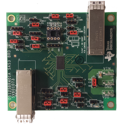
The mini-SAS HD cable running from the system ASIC to the DS125BR401A (Table 4, Column 2) connects to the top connector on the DS125BR401A SAS board given the orientation shown in Figure 8. The mini-SAS HD cable running from the DS125BR401A to the system ASIC (Table 4, Column 4) connects to the bottom connector.
 Figure 8. TIDA-00425, 12 Gbps SAS-3 Link Extender Board
 Although testing was completed with DS124BR401A CTLE = 0x03’h for Channel A, lower levels of equalization should be used if the attenuation between the SAS-3 ASIC Tx and the DS125BR401A inputs is less than 8-10 dB at 6 GHz.
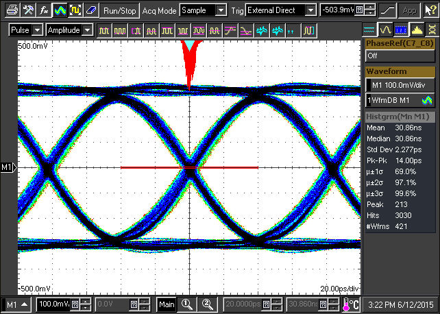
With the miniSAS-HD cables removed, the TIDA-00425 “SAS-3 Link Extender” design can be tested directly using SMA to miniSAS-HD breakout cables. Under this condition, high quality waveforms are observed on the output ports.
 Figure 9. 12 Gbps SAS-3 Waveform Output from “Link Extender Board”
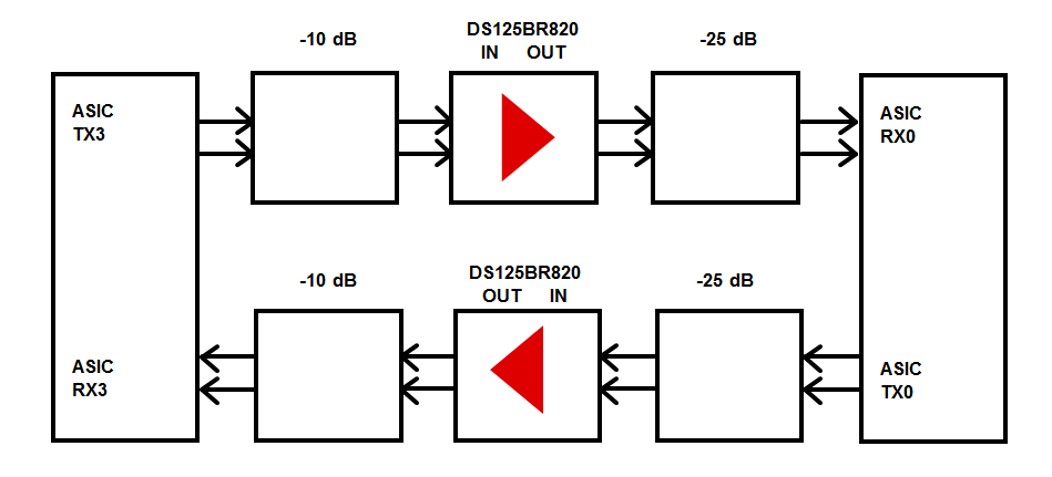
 Additional testing with the DS125BR820 using the setup in Figure 10 shows SAS-3 channel extension of approximately 10 dB is possible with good isolation between channels. This diagram shows DS125BR820 placement at both 10 dB and 25 dB away from the SAS-3 ASIC Tx. Further testing verified that all locations between 10 – 25 dB resulted in error free system performance.
 Figure 10. 12 Gbps SAS-3 Testing with System ASIC