SNIK005 august 2023 TMP9R00-SP
3.1 SEL Results
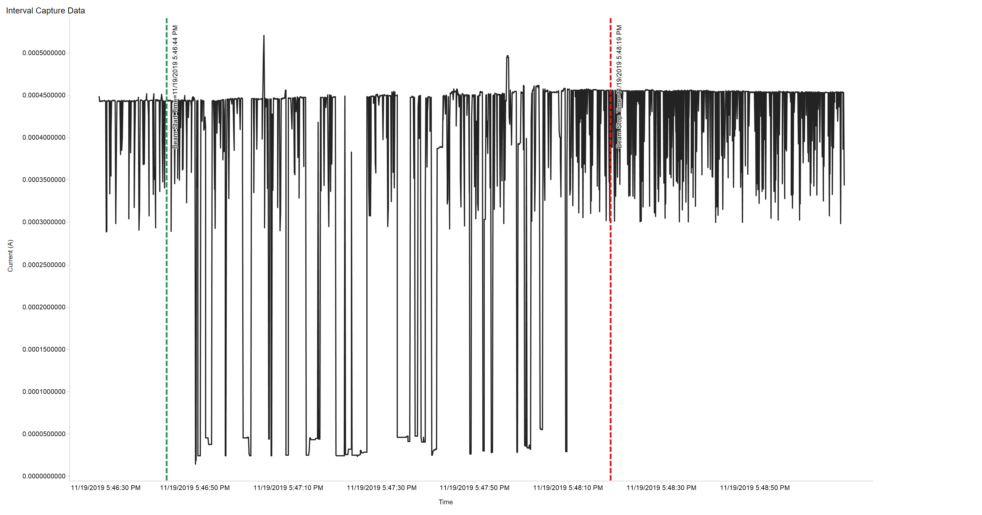
During SEL characterization, the device was heated using forced hot air, maintaining the die temperature at 125°C. The temperature was monitored by means of a K-type thermocouple attached as close as possible to the die. The species used for the SEL testing was a Thulium ion with angle of incidence at 0° and 29° for an LETEFF = 66 and 75 MeV-cm2/mg. A flux of approximately 105 ions/cm2 -s and a fluence of approximately 107 ions were used for all runs. The VCC voltage was set to the recommended maximum at 2.0 V. No SEL events were observed during both runs, as shown in Table 3-2. The resulting graph of current vs time is detailed in Figure 3-1.
| Run # | Distance (mm) | Temperature (°C) |
Ion Type | Angle of Incidence | Flux (ions·cm2/mg) |
Fluence (ions/cm2) |
LETEFF (MeV-cm2/mg) |
|---|---|---|---|---|---|---|---|
| 1 | 40 | 125 | Tr | 0° | 1.00 × 10⁵ | 1.00 × 10⁷ | 66 |
| 2 | 40 | 125 | Tr | 29° | 1.00 × 10⁵ | 1.00 × 10⁷ | 75 |
 Figure 3-1 Current vs Time for
VCC Supply During SEL Run #2