SNAA357 September 2022 LMX2820
2 Test Results
The following figures show the mute and unmute time of the LMX2820 RF output in response to the status of the MUTE pin (green trace). The RF switch is not included in following measurement plots.
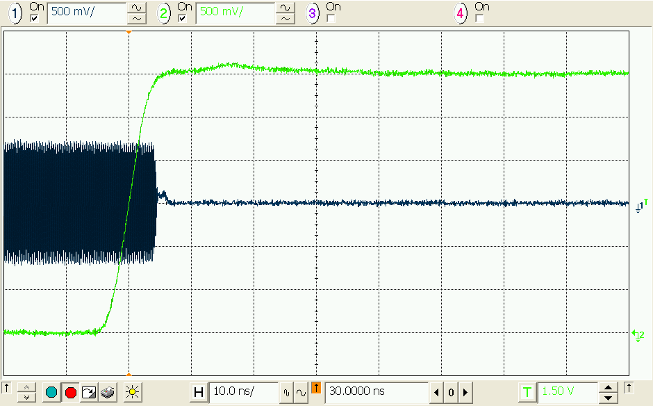 Figure 2-1 LMX2820 RFOUT Mute Time
(Active High)
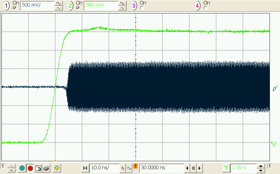 Figure 2-3 LMX2820 RFOUT Unmute Time
(Active Low)
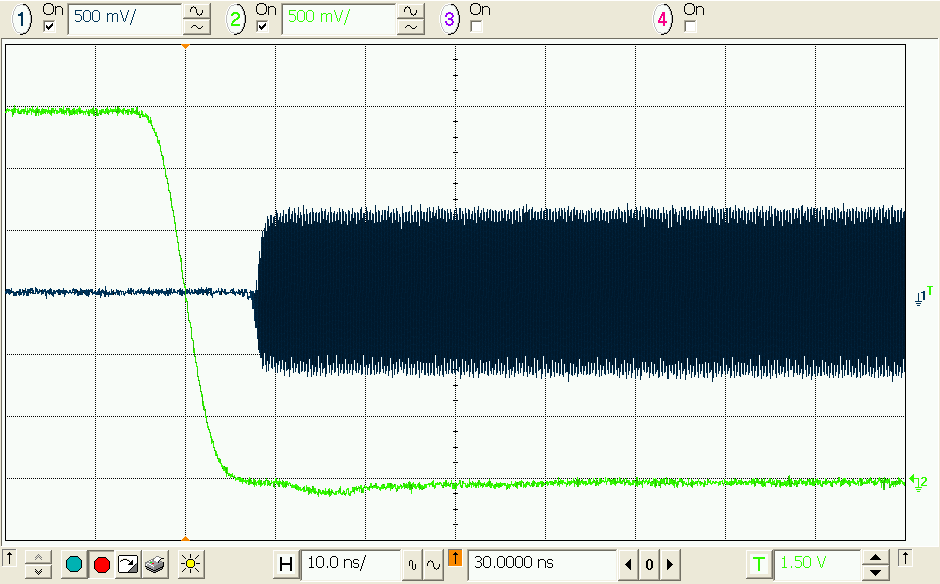 Figure 2-2 LMX2820 RFOUT Unmute Time
(Active High)
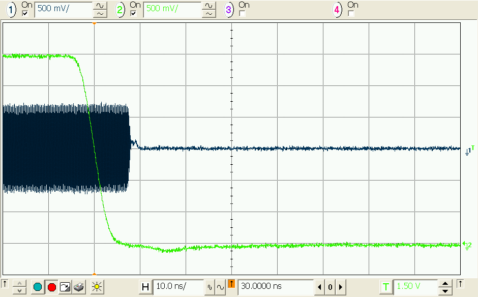 Figure 2-4 LMX2820 RFOUT Mute Time
(Active Low)
Figure 2-4 LMX2820 RFOUT Mute Time
(Active Low)MUTE pin response time is very short. In less than 10 ns, LMX2820 output can be muted or unmuted completely.
Combining MUTE with the RF switch, the output signal of the RF switch is shown in the following figures. Whenever the mute control signal flips over, RF switch selected the alternate input channel with some delay. Turn-on time of the switch is kind of slow, however.
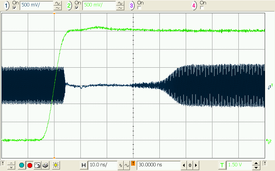 Figure 2-5 RF Switch Output - MUTE
Rising
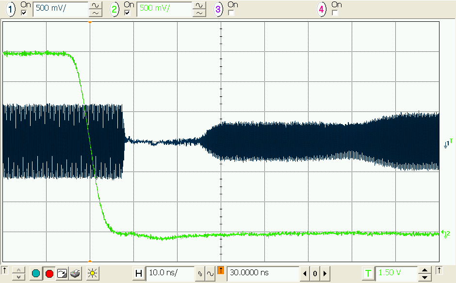 Figure 2-6 RF Switch Output - MUTE
Falling
Figure 2-6 RF Switch Output - MUTE
FallingDisregarding the on-time characteristic of the chosen RF switch being used in this report, the overall switching time is around 30 ns to 40 ns.
Figure 2-7 shows the ping-pong switching characteristic in frequency-time domain. One of the LMX2820 is programmed to 5.7 GHz and the other one is programmed to 6 GHz. Mute control is a 2 kHz signal, the output of the RF switch is therefore toggling between 5.7 GHz and 6 GHz every 250 µs.
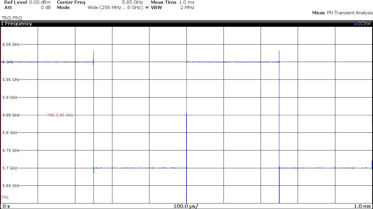 Figure 2-7 RF Switch Output
The following figures show the attenuation from the MUTE function, isolation from the RF switch and the combination of both MUTE and RF switch. Blue trace and black trace represents the output signal when the selected channel is activated and deactivated respectively.
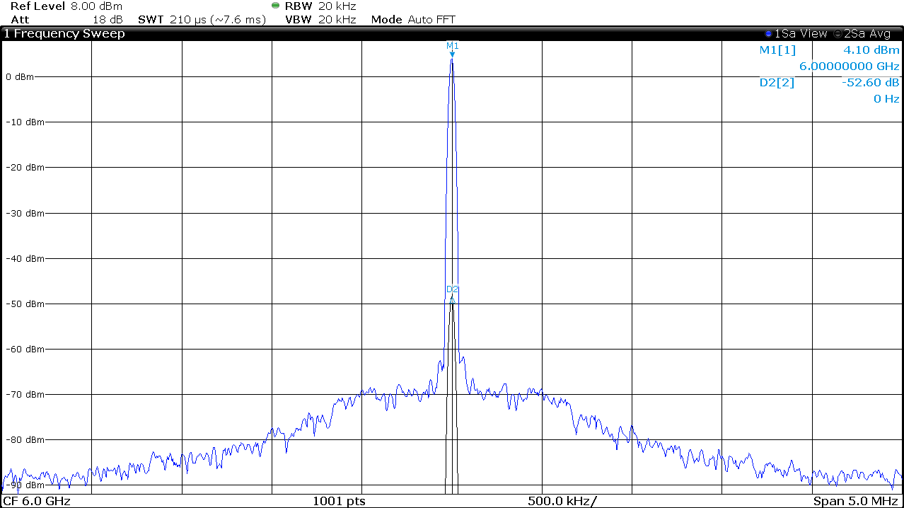 Figure 2-8 MUTE Pin Attenuation - 6
GHz
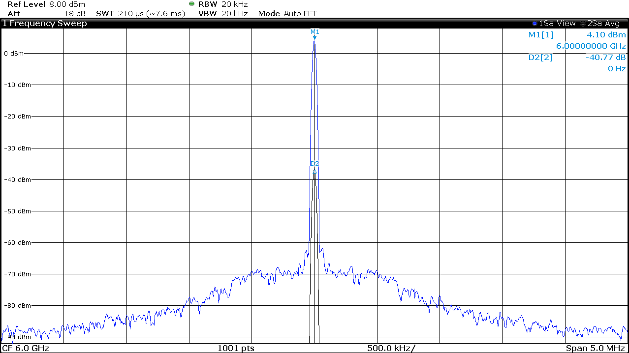 Figure 2-10 RF Switch Isolation - 6
GHz
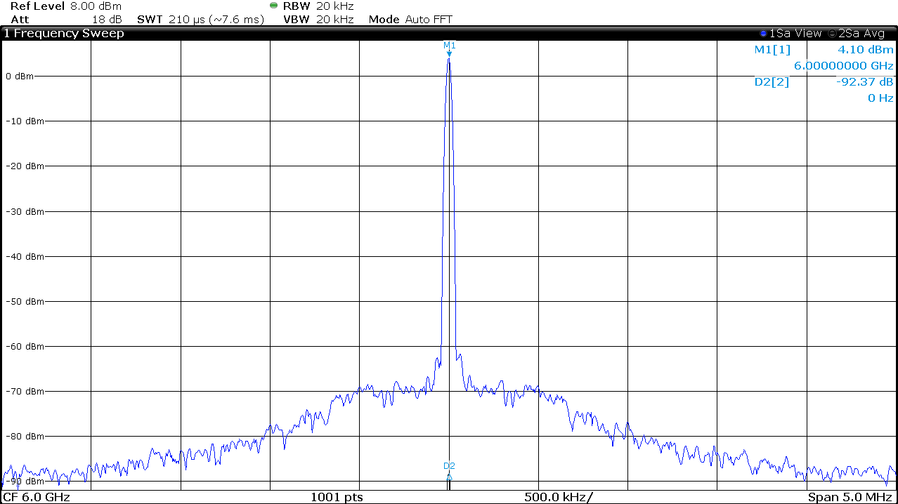 Figure 2-12 Total Isolation - 6
GHz
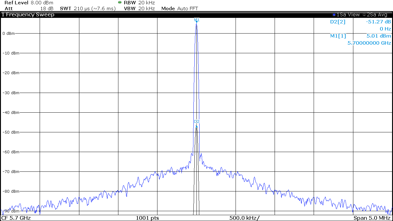 Figure 2-9 MUTE Pin Attenuation - 5.7
GHz
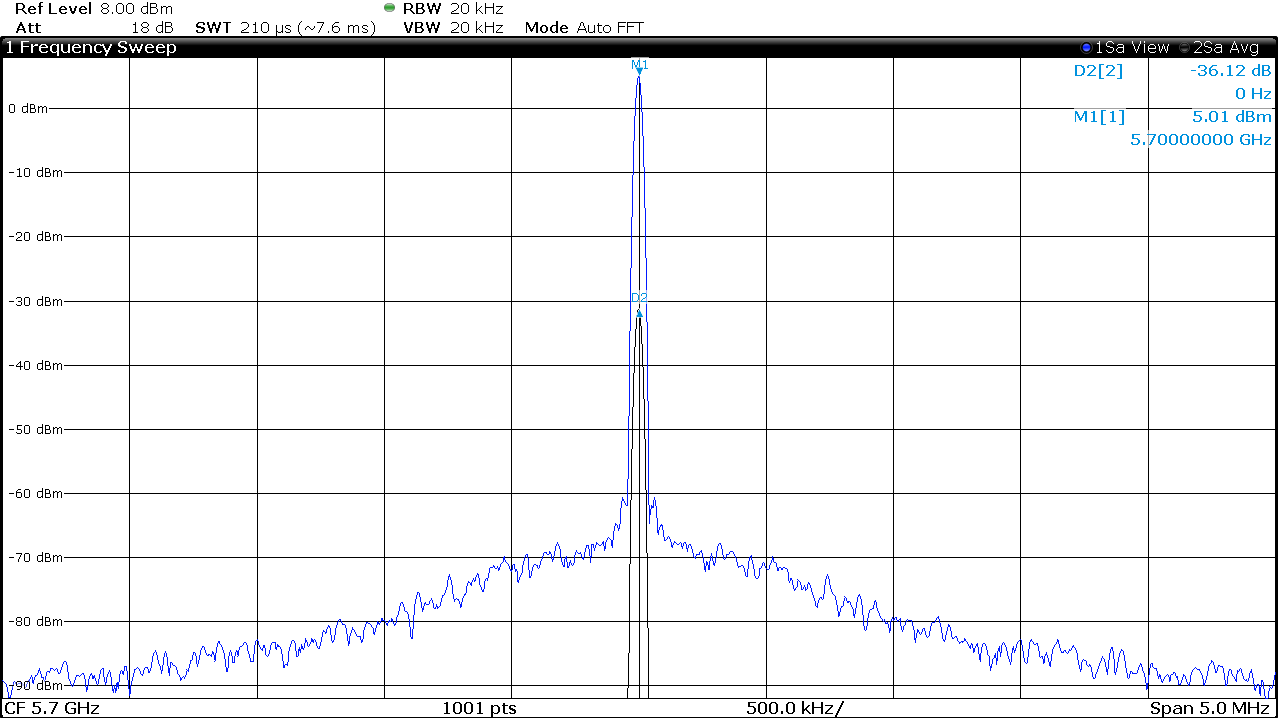 Figure 2-11 RF Switch Isolation - 5.7
GHz
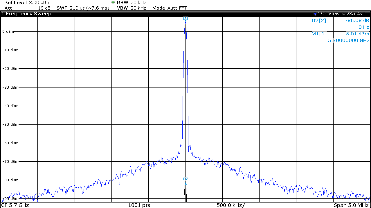 Figure 2-13 Total Isolation - 5.7
GHz
Figure 2-13 Total Isolation - 5.7
GHzAttenuation from the MUTE pin is approximately 50 dB. RF switch provides another 36 to 40 dB isolation. The total attenuation when the channel is unmuted and switched out is 86 to 90 dB. In other words, when one of the LMX2820 is routed to the output of the RF switch, the user can continue to measure the signal from the other LMX2820 with an isolation of 86 to 90 dB.