SLVUBV4A December 2020 – December 2021 TPS272C45
6 TPS272C45EVM Assembly Drawings and Layout
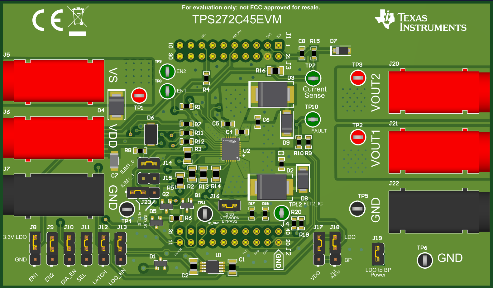 Figure 6-1 3D Representation
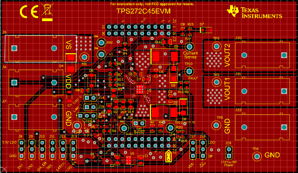 Figure 6-2 Top Layer
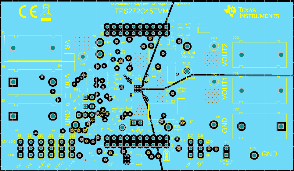 Figure 6-3 Power Layer
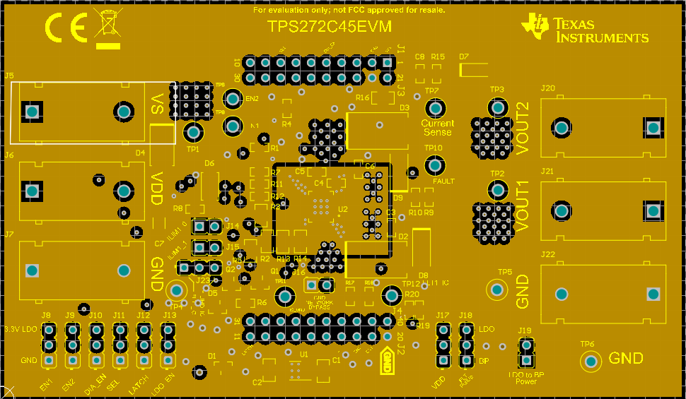 Figure 6-4 Ground Layer
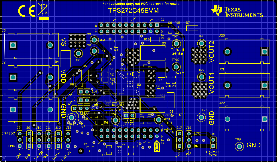 Figure 6-5 Bottom Layer
SLVUBV4A December 2020 – December 2021 TPS272C45
 Figure 6-1 3D Representation
 Figure 6-2 Top Layer
 Figure 6-3 Power Layer
 Figure 6-4 Ground Layer
 Figure 6-5 Bottom Layer