SLVUBR5D August   2019  – November 2021 TPSM82821 , TPSM82822 , TPSM82823


  1. 1TPSM8282xEVM-080 and TPSM8282xAEVM-127 Evaluation Modules
  2. 2Introduction
    1. 2.1 Performance Specification
    2. 2.2 Modifications
      1. 2.2.1 Input and Output Capacitors
  3. 3Setup
    1. 3.1 Setup
    2. 3.2 Input/Output Connector Descriptions
  4. 4Safety Instructions
  5. 5TPSM8282xEVM-080 Test Results
  6. 6Board Layout
  7. 7Schematic and Bill of Materials
    1. 7.1 Schematic
    2. 7.2 Bill of Materials
      1.      A Appendix - Rev.A EVM
        1.       A.1 Rev.A - Input and Output Capacitors
        2.       A.2 Rev.A - Setup
          1.        A.2.1 Rev.A - Setup
          2.        A.2.2 Rev.A - Input/Output Connector Descriptions
        3.       A.3 Rev.A - Board Layout
        4.       A.4 Rev.A - Schematic and Bill of Materials
          1.        A.4.1 Rev.A - Schematic
          2.        A.4.2 Rev.A - Bill of Materials
            1.         B Revision History

Rev.A - Board Layout

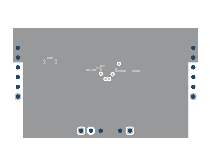
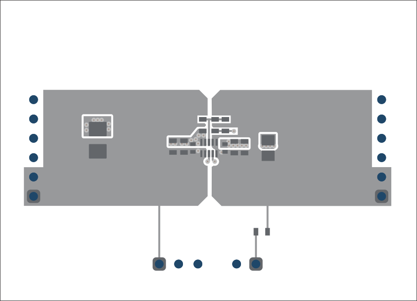
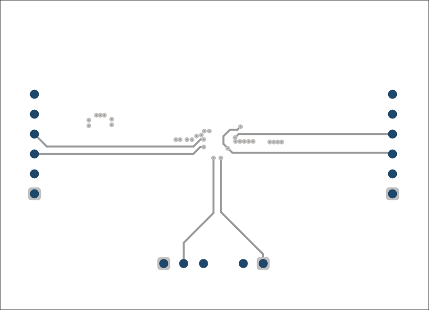
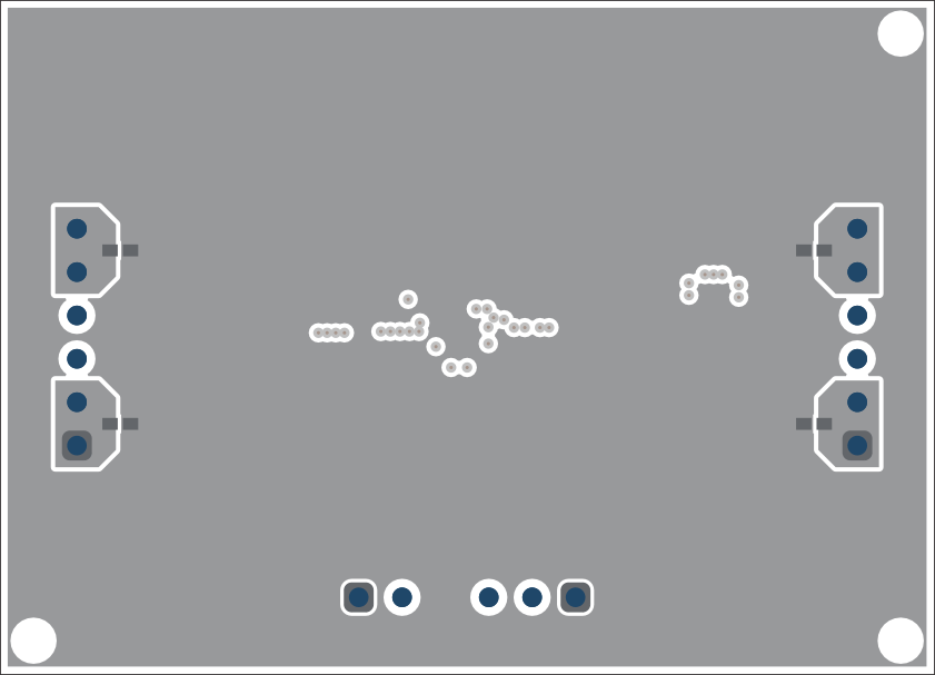
This section provides the TPSM8282xEVM-080 Revision A board layout and illustrations in Figure 8-1 through Figure 8-5.
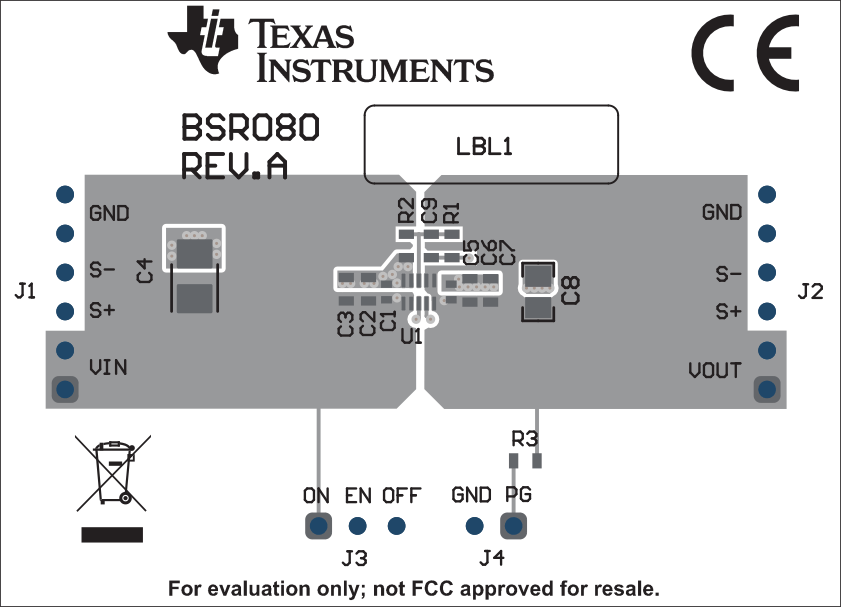
GUID-8B27CED1-F20B-4960-AB8D-50A9BB9FE12C-low.gifFigure 8-1 Rev.A - Top Assembly
GUID-9D07ADFC-7746-4880-8671-E2E5DF3F6874-low.gifFigure 8-3 Rev.A - Signal Layer 1
GUID-E2BFF829-176F-427B-934B-9CB0CD4C87E6-low.gifFigure 8-2 Rev.A - Top Layer
GUID-22B4FB99-2C16-4723-BAC2-4A1858037FBA-low.gifFigure 8-4 Rev.A - Signal Layer 2
GUID-603C754C-7841-4319-AB0D-C0D289DEF106-low.gifFigure 8-5 Rev.A - Bottom Layer