SLVAES8 May 2020 DRV8424 , DRV8424E , DRV8426 , DRV8428 , DRV8428E , DRV8434 , DRV8434E , DRV8434S , DRV8436 , DRV8436E , DRV8889-Q1
3.3.1 Effects of Current Ripple and Decay Mode
The smoothest and quietest operation of a stepper motor happens when perfect sinusoidal current waveforms are applied to the windings. Any ripple in the current waveform is a deviation from the desired shape and causes an uneven torque in the motor, which manifests as vibration and noise during operation. To reduce the ripple and therefore audible noise, it is recommended to operate a stepper motor on slow decay mode whenever possible, instead of fast or mixed decay.
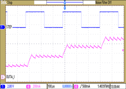 Figure 5. Microstepping Current vs STEP Input, Slow Decay
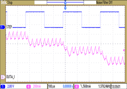 Figure 6. Microstepping Current vs STEP Input, Mixed Decay
Figure 5 and Figure 6 show the current ripple in slow decay and fixed-percentage mixed decay, respectively, for the same operating conditions. Current ripple is roughly 50 mA with slow decay, but close to 200 mA when the decay mode is changed to traditional mixed decay with 30% fast decay.
However, due to back-emf, mixed decay modes are better at following the ideal sinusoidal current waveform, especially at high speeds and on decreasing steps, compared to slow decay, as shown in Figure 7 and Figure 8 for mixed decay and slow decay respectively. Therefore, a slow decay mode which can follow the ideal waveform at all conditions is the ideal candidate for reducing audible noise from stepper motors.
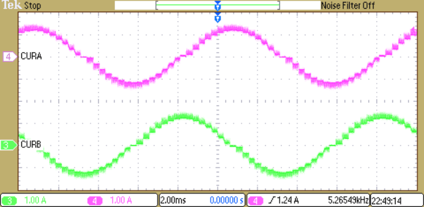 Figure 7. 30% Mixed Decay on Increasing and Decreasing Steps
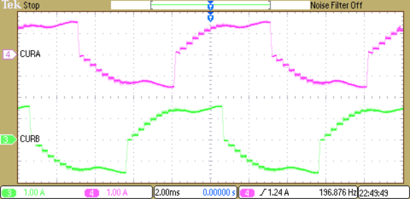 Figure 8. Slow Decay on Increasing and Decreasing Steps
The smart tune Ripple Control (STRC) mode featured in several stepper motor drivers from Texas Instruments is one such slow decay scheme. As shown in Figure 9, smart tune Ripple Control operates by setting an IVALLEY level alongside the ITRIP level. When the current level reaches ITRIP, instead of entering slow decay until the tOFF time expires, the driver enters slow decay until IVALLEY is reached.
Therefore, this mode allows much tighter regulation of the ripple current than traditional mixed decay schemes. In this mode, tOFF varies depending on the current level and operating conditions. On decreasing steps, smart tune Ripple Control automatically switches to fast decay to reach the next step quickly - which enables it to follow the ideal sinusoidal current waveform at all speeds.
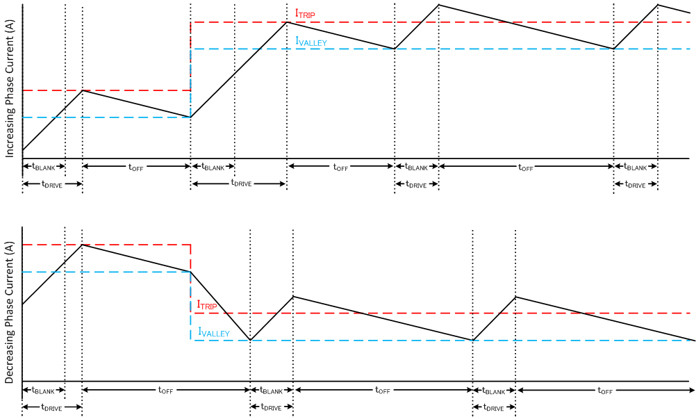 Figure 9. Smart tune Ripple Control Decay Mode
 Table 1 lists various stepper motor drivers which feature the smart tune Ripple Control decay mode.
Table 1. Stepper Motor Drivers With Smart Tune Ripple Control
| Device | Operating Supply Voltage Range | Full-Scale Current | RDS(ON) (HS + LS) | Microstepping |
|---|---|---|---|---|
| DRV8428 | 4.2 - 33 V | 1 A | 1500 mΩ | 1/256 |
| DRV8899-Q1 | 4.5 - 45 V | 1 A | 1200 mΩ | 1/256 |
| DRV8889-Q1 | 4.5 - 45 V | 1.5 A | 900 mΩ | 1/256 |
| DRV8436 | 4.5 - 48 V | 1.5 A | 900 mΩ | 1/256 |
| DRV8426 | 4.5 - 33 V | 1.5 A | 900 mΩ | 1/256 |
| DRV8425 | 4.5 - 33 V | 2 A | 550 mΩ | 1/256 |
| DRV8886AT | 8 - 37 V | 2 A | 550 mΩ | 1/16 |
| DRV8424 | 4.5 - 33 V | 2.5 A | 330 mΩ | 1/256 |
| DRV8434 | 4.5 - 48 V | 2.5 A | 330 mΩ | 1/256 |
The ability to tightly control the ripple current gives smart tune Ripple Control better audio performance than mixed decay schemes. Figure 10 compares the SPL plots of DRV8424 smart tune Ripple Control and mixed decay at 1/256 microstepping. As can be seen, smart tune Ripple Control (green) has up to 10dB lower noise beyond 4kHz than mixed decay (purple). Smart tune Ripple Control only causes an almost inaudible hissing noise, while there is a whining noise when the motor runs with mixed decay.
As is well known, every 3dB reduction in decibel level corresponds to halving of sound energy, and every 10dB reduction corresponds to sound energy decrease by a factor of 10. Therefore, at certain frequencies, smart tune Ripple Control generates only 10% of the noise generated by mixed decay modes.
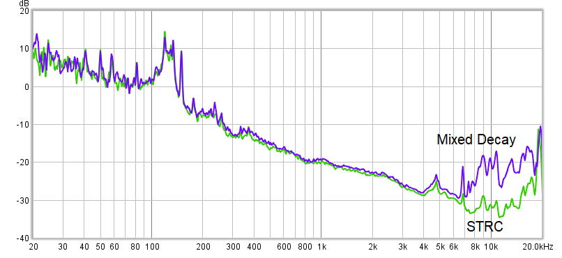 Figure 10. Mixed Decay vs Smart Tune Ripple Control (STRC) at 1/256 Microstepping
 The impact of lower ripple current is further illustrated by Figure 11. For the DRV8424, DRV8425 and DRV8426 devices, the ripple current level in smart tune ripple control mode can be adjusted by the TOFF pin. The SPL plot in Figure 11 compares audible noise among the different ripple current settings. 1% and 2% ripple current settings have almost the same ripple current, roughly 50 mA at peak of the sinusoid, due to comparator offset, and so forth. Based on the graph, 1% (green) and 2% (blue) ripple settings show the best audio performance and the 6% ripple (orange) has the worst audio performance over the entire spectrum.
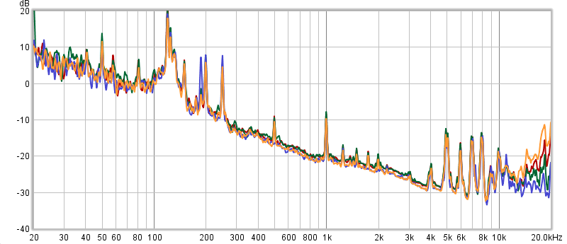 Figure 11. Effects of Changing Current Ripple