SLUUC71 May 2021
2.1 Features
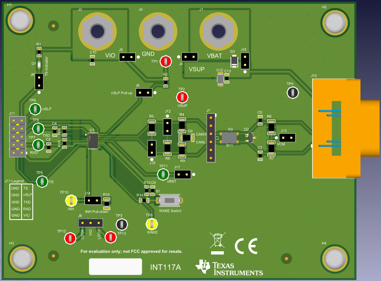
This EVM supports the following features:
- Standard and split termination on the CAN bus.
- Footprints for filter capacitors, common-mode choke, and TVS diode for CAN bus protection from RF noise and transient pulses.
- DSUB9 connector with the CAN bus signals, VBAT, and GND for typical automotive cable harness connections.
- All digital signals for configuration and control brought out to a header for easy access.
- Pushbutton WAKE circuit for easy local wake.
- Monitoring points for CAN bus common-mode.
- Option to supply VIO with integrated LDO on the TCAN11625-Q1 and TCAN11623-Q1.
- Transceiver status indicator LED for monitoring fault conditions.
 Figure 2-1 EVM Photo