SLUAAL7 September 2022 BQ35100
2 EVM and System Setup
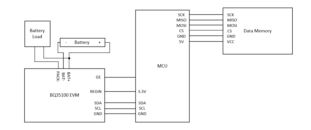
Figure 2-1 shows the wiring used for collecting impedance data. The BQ35100 EVM is connected using I2C communication, and data memory is connected using SPI communication, or any other available method. The BQ35100 EVM already implements pull-up resistors on the I2C communication lines so no external pull-up resistors are needed.
Any controller or MCU can be used for collecting the impedance data, there are only a few requirements:
- The ability to save logged data read from the BQ35100
- Ability to communicate over I2C to read data and send commands
- GPIO functionality for the GE and ALERT functions
 Figure 2-1 Wire Connection Block Diagram