SLUAA66 May 2020 UCC28740
1 Introduction
The flyback converter represents very popular structure found in the market due to its simplicity, ease of design and low cost. And, the flyback operated in current mode is the most widely used converter having first-order behavior in the low-frequency portion. The UCC28740 is a flyback power-supply controller which combines frequency with primary peak-current amplitude modulation to provide high conversion efficiency across the load range.
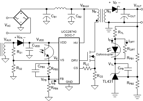
Figure 1 shows the typical application circuit of the UCC28740. The circuit that has become very widespread is where the TL431 is used in conjunction with an optocoupler to provide feedback loop isolation. Note that several of the components including the TL431, an optocoupler, CFB, CFB3, RTL, RFB3 and RFB4 are involved in making the loop stable. In this circuit, the output of the TL431 is powered through the resistor RTL and the optocoupler diode, connected in series with the power supply output.
 Figure 1. Typical Application Circuit of the UCC28740
 The main effect is that the gain of the circuit is now driven by the current into the output of the TL431, not by its output voltage. This current is determined by the voltage gain of the TL431, the supply voltage to the top of RTL and the value of RTL itself.