SLUAA66 May 2020 UCC28740
3 Experimental Results
The components including Copto, CFB3, RFB3 and RFB4 are important to determine the dominant pole position properly, and the value of RFB4 is usually in the range from 10 kΩ to 100 kΩ. A tradeoff must be made between a lower value for faster transient response and a higher value for lower standby power
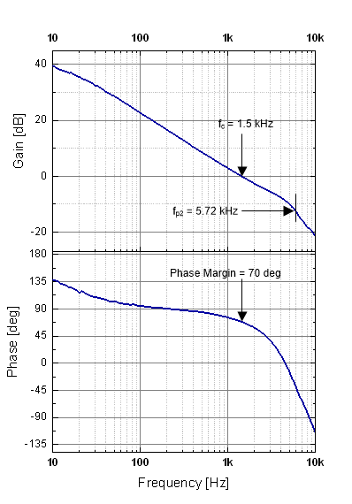
Figure 6 shows the loop gain and the phase margin of applying CFB3, RFB3, RFB4, Copto values to a flyback converter example. And, the UCC28740 EVM-525 is used for this measurement. As shown in Figure 6, the crossover frequency, with a 110 VAC, 60 Hz input and load current of 1 A, is limited to about 1.5 kHz passing it through with -1 gain slope (-20 dB/decade), and the phase margin measured to be 70 degrees at this crossover frequency. The actual location of the dominant pole (fP2) is about 5.72 kHz as it is already calculated in Equation 12.
 Figure 6. Loop Gain and Phase Margin
 The gain drops off rapidly with -2 gain slope (-40 dB/decade) after this pole frequency, and the gain margin measured to be -8 dB when the phase is zero degrees.