SLOA312 December 2021 DRV8412 , DRV8424 , DRV8426 , DRV8428 , DRV8434 , DRV8436 , DRV8803 , DRV8804 , DRV8805 , DRV8806 , DRV8844 , DRV8847 , DRV8932 , DRV8935 , DRV8955
PRODUCTION DATA
3.3.2 Driving in Half-step Mode
The truth table for this mode of operation is shown in Table 3-6.
Table 3-6 Truth Table
| INDEX | IN1 | IN2 | IN3 | IN4 |
|---|---|---|---|---|
| 1 | 0 | 1 | 1 | 1 |
| 2 | 0 | 0 | 1 | 1 |
| 3 | 1 | 0 | 1 | 1 |
| 4 | 1 | 0 | 0 | 1 |
| 5 | 1 | 1 | 0 | 1 |
| 6 | 1 | 1 | 0 | 0 |
| 7 | 1 | 1 | 1 | 0 |
| 8 | 0 | 1 | 1 | 0 |
| 9 | 0 | 1 | 1 | 1 |
| 10 | 0 | 0 | 1 | 1 |
| 11 | 1 | 0 | 1 | 1 |
| 12 | 1 | 0 | 0 | 1 |
| 13 | 1 | 1 | 0 | 1 |
| 14 | 1 | 1 | 0 | 0 |
| 15 | 1 | 1 | 1 | 0 |
| 16 | 0 | 1 | 1 | 0 |
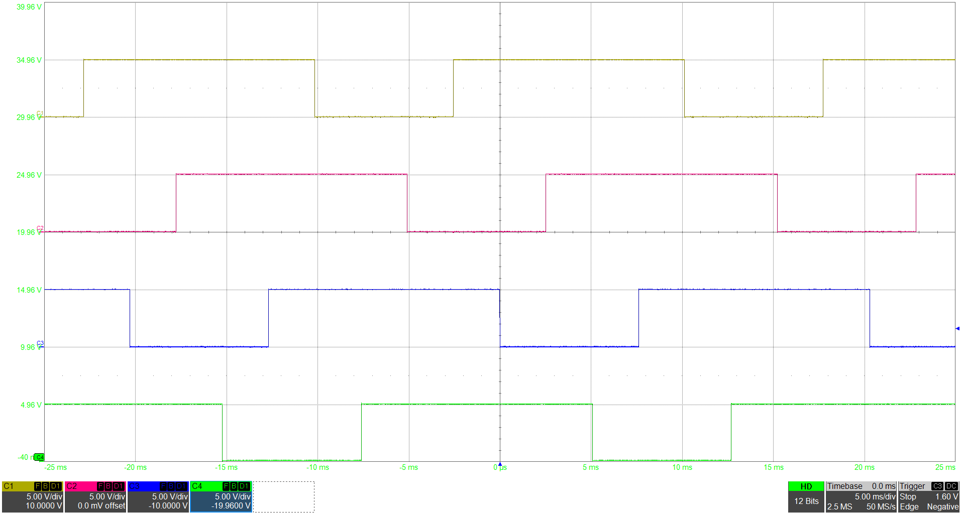
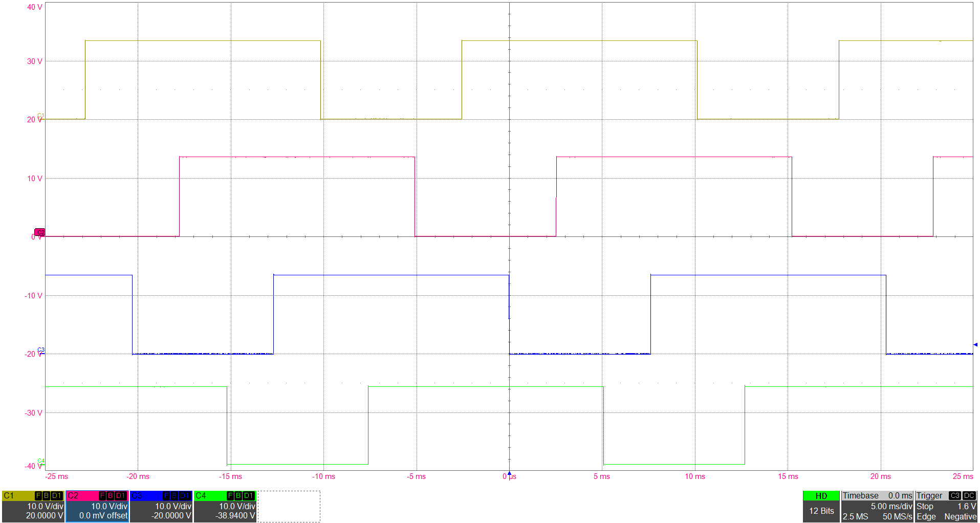
Figure 3-10 and Figure 3-11 show the input and output waveforms when driving a unipolar stepper motor in half step mode with the DRV8935.
 Figure 3-10 Input PWM signal of
DRV8935
 Figure 3-11 Output node waveforms of
DRV8935