SLLU321 July 2022
- TCAN1043AEVM Evaluation Module User's Guide
- Trademarks
- 1Introduction
- 2Test Setup and Results
- 3EVM Setup and Basic Usage
- 4Schematic and Bill of Materials
2.1.5 nSTB and EN Mode Control
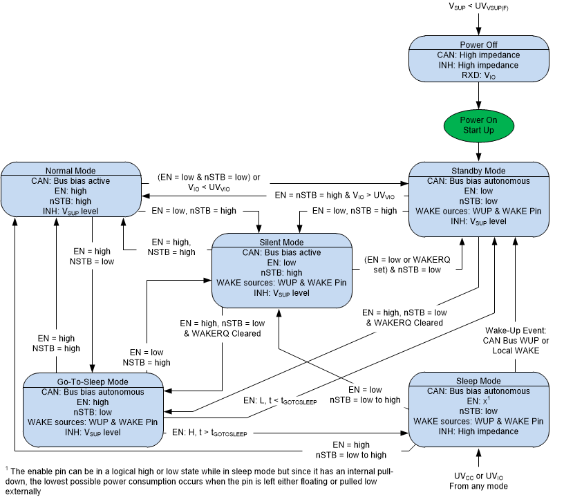
The device has four main operating modes: normal mode, standby mode, silent mode and sleep mode, and one transitional mode called go-to-sleep mode. Operating mode selection is made through the nSTB and EN input terminals in conjunction with supply conditions and wake events. Table 2-2 lists the operational modes of the device and the associated pin configurations. Figure 2-1 shows a state diagram of the various device modes with the associated pin configurations. Use TCAN1043 Automotive Fault Protected CAN Transceiver With CAN FD as an additional reference to the EVM.
| VCC and VIO | VSUP | EN | nSTB | WAKERQ Flag |
Mode | Driver | Receiver | RXD | Bus Bias | INH |
|---|---|---|---|---|---|---|---|---|---|---|
| Good | Good | H | H | X | Normal | Enabled | Enabled | Mirror Bus State | VCC/2 | On |
| Good | Good | L | H | X | Silent | Disabled (Off) | Enabled | Mirror Bus State | VCC/2 | On |
| Good | Good | H | L | Cleared | Go to Sleep | Disabled (Off) | Low Power Bus Monitor (On) | High or High Z (No VIO) | Weak pull to GND | On |
| Cleared | Sleep | Disabled (Off) | Low Power Bus Monitor (On) | High or High Z (No VIO) | Weak pull to GND | Off | ||||
| Set | Standby | Disabled (Off) | Low Power Bus Monitor (On) | High or High Z (No VIO) | Weak pull to GND | On | ||||
| Good | Good | L | L | X | Standby | Disabled (Off) | Low Power Bus Monitor (On) | High or High Z (No VIO) | Weak pull to GND | On |
| Bad | Good | X | X | X | Sleep | Disabled (Off) | Low Power Bus Monitor (On) | High or High Z (No VIO) | Weak pull to GND | Off (High Z) |
| X | Bad | X | X | X | Protected | Disabled (Off) | Disabled (Off) | High Z | High Z | Off (High Z) |
 Figure 2-1 TCAN1043A-Q1 State
Diagram
Figure 2-1 TCAN1043A-Q1 State
DiagramThe EN signal is available via JMP2 position 4 and TP5.
The nSTB pin is available via JMP2 position 1 and JMP1. JMP1 and JMP2 provide a local GND connection next to the INH pin to enter standby mode. nSTB incorporates a 4.7-kΩ pullup resistor, R1.